Supercharge Your Innovation With Domain-Expert AI Agents!

Bridge deck laying device

A technology for laying devices and bridges, applied in bridge construction, bridges, bridge parts, etc., can solve the problems of reducing the efficiency of bridge deck laying and increasing the work flow, and achieve the effect of simple structure and convenient operation.

Active Publication Date: 2019-04-23
广西桂资工程集团有限公司
View PDF7 Cites 0 Cited by
  • Summary
  • Abstract
  • Description
  • Claims
  • Application Information

AI Technical Summary

Problems solved by technology

[0002] At present, in the process of bridge construction, asphalt needs to be laid on the surface of the bridge deck after the treatment of the base layer of the bridge deck is completed. The traditional method requires separate equipment to mix and process the asphalt first and then lay it evenly on the bridge deck, thus increasing the cost of workflow and reduced bridge deck laying efficiency

Method used


Image

  • Bridge deck laying device
  • Bridge deck laying device
  • Bridge deck laying device

Examples


Embodiment Construction

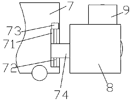
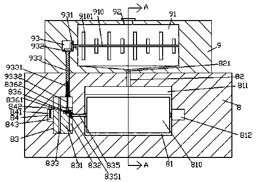
[0016] Such as Figure 1-Figure 4 As shown, a bridge deck laying device for a bridge of the present invention includes a driving body 7 and a laying frame installed on the front side of the driving body 7, and the laying frame is composed of an upper frame 9 and a lower frame 8 , the front end surface of the driving body 7 is provided with a lifting groove 71 extending up and down, and a lifting block 74 is slidably connected to the lifting groove 71, and a main shaft extending up and down is connected to the lifting block 74 in a spiral fit. Screw-shaped rod 72, the front side end of the lifting block 74 penetrates the outside of the driving body 7 and is fixedly connected with the rear side end surface of the lower frame 8, and the bottom of the main screw-shaped rod 72 is extended. The slot 71 is rotationally fitted and connected, and the extension tail at the top of the main screw rod 72 is connected with the main driving machine 73. A cavity 81 is provided in the front e...


PUM


Abstract

The invention discloses a novel bridge floor laying device used for a bridge. The novel bridge floor laying device used for the bridge comprises a driving vehicle body and a laying rack installed at the front side end of the driving vehicle body. An ascending and descending groove extending up and down is formed in the front side end face of the driving vehicle body. An ascending and descending block is connected to the inside of the ascending and descending groove in a sliding fit mode. A main spiral rod extending up and down is connected to the inside of the ascending and descending block ina spiral fit mode. The front side end of the ascending and descending block penetrates out of the driving vehicle body and is connected with the rear side end face of a lower rack in a fixed fit mode. The extending tail portion at the top of the main spiral rod is connected with the ascending and descending groove in a running fit mode. The extending tail portion at the bottom of the main spiralrod is connected with a main driver. The outer surface of the main driver is installed in the bottom wall in the ascending and descending groove and fixedly connected with the bottom wall in the ascending and descending groove. The novel bridge floor laying device used for the bridge is simple in structure and convenient to operate, and the work efficiency and the bridge floor laying quality are improved.

Description

technical field [0001] The invention relates to the technical field of bridges, in particular to a bridge deck laying device for bridges. Background technique [0002] At present, in the process of bridge construction, asphalt needs to be laid on the surface of the bridge deck after the treatment of the base layer of the bridge deck is completed. The traditional method requires separate equipment to mix and process the asphalt first and then lay it evenly on the bridge deck, thus increasing the cost of Workflow and reduced bridge deck laying efficiency. Contents of the invention [0003] The technical problem to be solved by the present invention is to provide a bridge deck laying device for bridges, which can solve the above-mentioned problems in the prior art. [0004] The present invention is achieved through the following technical solutions: a bridge deck laying device for a bridge of the present invention includes a driving body and a laying frame installed on the f...

Claims


Application Information

Patent Timeline
Patent Type & Authority Patents(China)
IPC IPC(8): E01D21/00E01D19/08
CPCE01D19/083E01D21/00
Inventor 何振辉
Owner 广西桂资工程集团有限公司
Features
  • R&D
  • Intellectual Property
  • Life Sciences
  • Materials
  • Tech Scout
  • Unparalleled Data Quality
  • Higher Quality Content
  • 60% Fewer Hallucinations
Learn More