Outer wall plate connecting piece and construction method

A technology for exterior wall panels and connectors, which is applied in covering/lining, construction, building construction, etc., which can solve the problems of inaccurate positioning and low precision of exterior wall panels, and achieve improved comprehensive installation efficiency, convenient processing, and simple structure Effect

Pending Publication Date: 2018-06-26
GRAND FACADE DECORATION ENG CO LTD
View PDF10 Cites 12 Cited by
  • Summary
  • Abstract
  • Description
  • Claims
  • Application Information

AI Technical Summary

Problems solved by technology

However, due to the low position accuracy of the embedded bolts on the exterior wall of the building, it often results in the inability to accurately position the exterior wall panels during installation. It is necessary for the connector to have the function of adjusting up, down, left, and right to realize the effective splicing of multiple exterior wall panels.

Method used


Image

  • Outer wall plate connecting piece and construction method
  • Outer wall plate connecting piece and construction method
  • Outer wall plate connecting piece and construction method

Examples


Embodiment 1

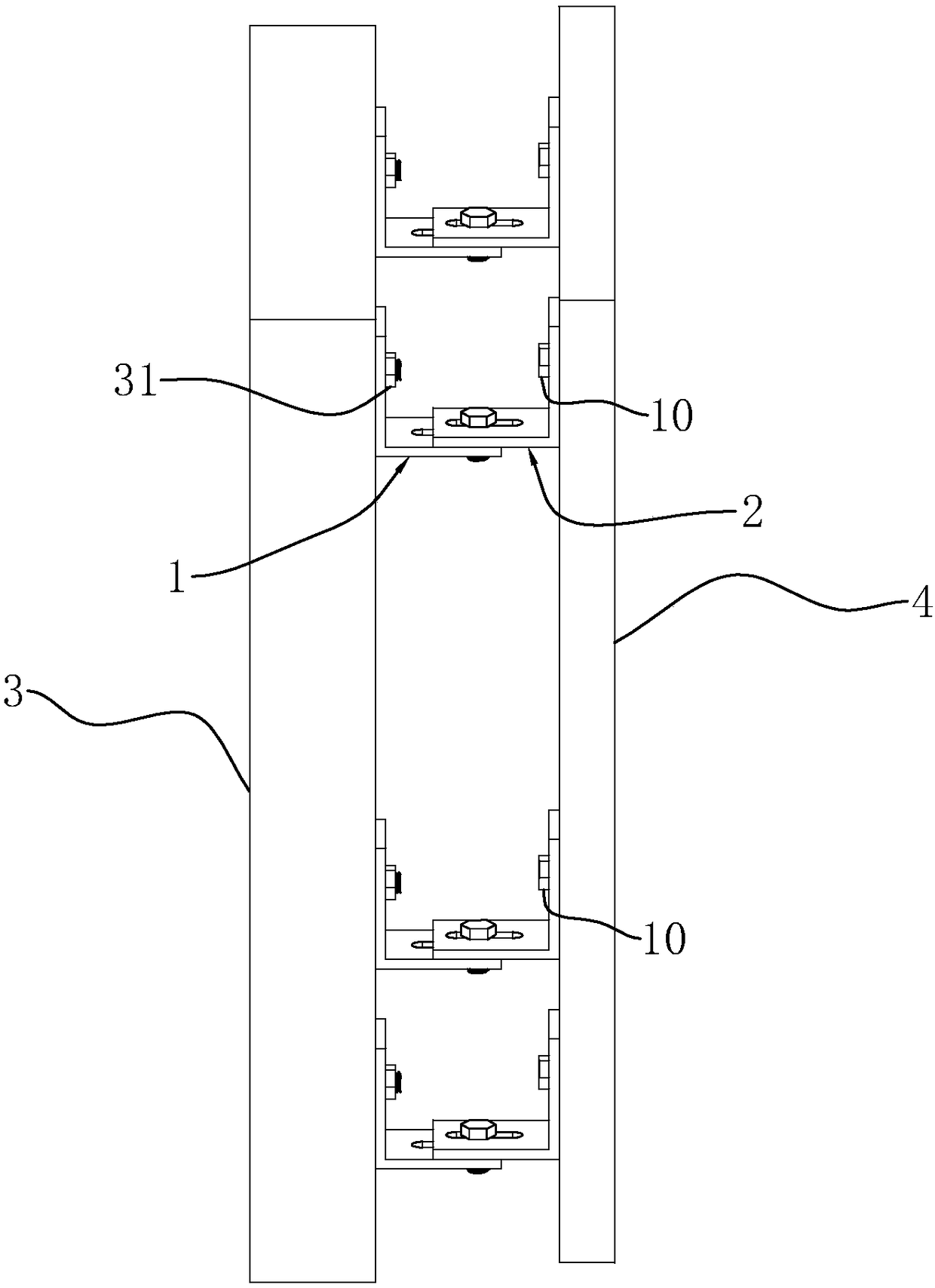
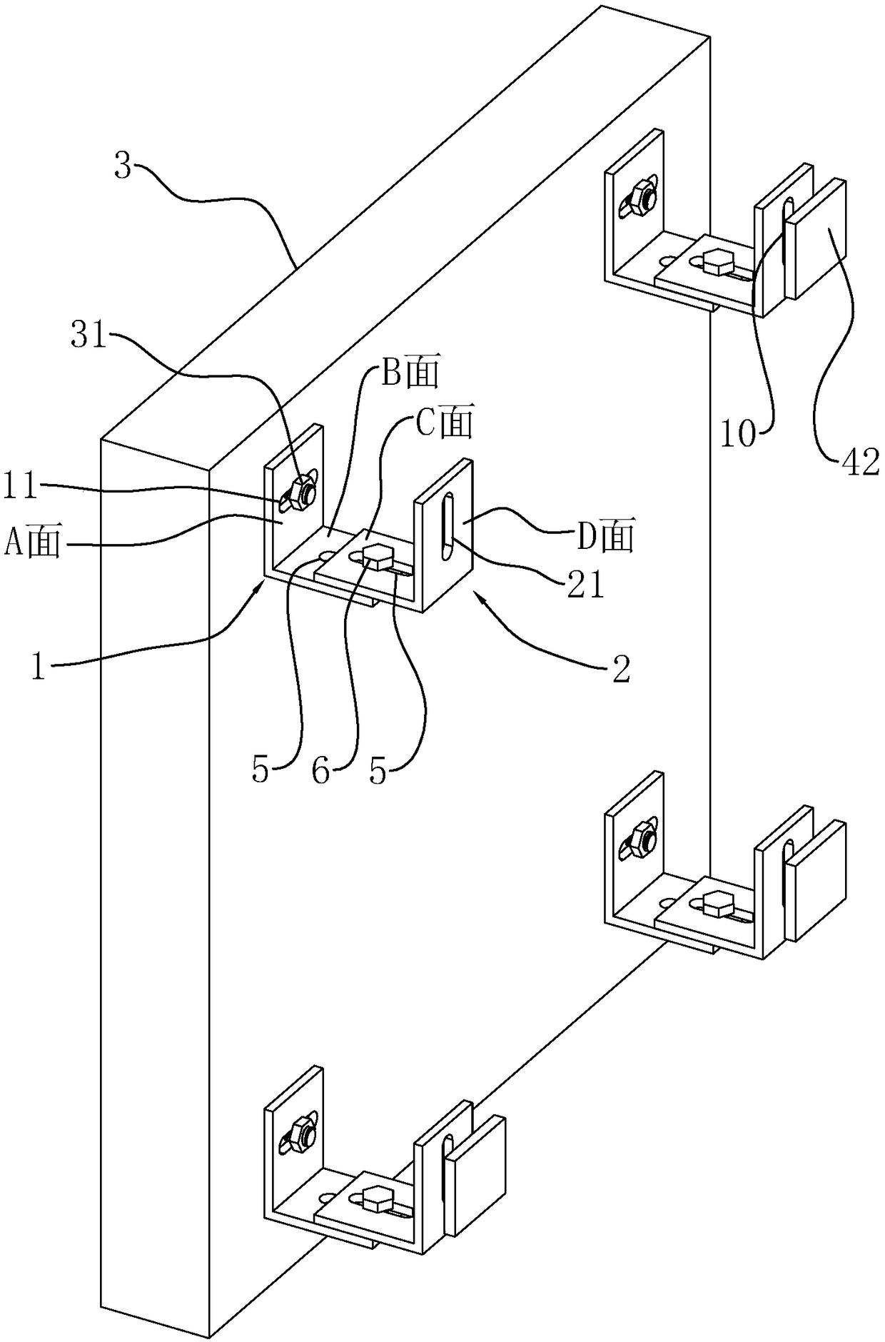
[0043] Such as figure 1 and figure 2 As shown, a connector is provided near the four corners of each exterior wall panel 4, and embedded bolts 31 ( figure 2 The exterior wall panel 4) is not shown in . The external wall panel connector includes a first angle steel 1 , a second angle steel 2 , a first bolt 6 and a second bolt 10 . The first angle steel 1 includes a surface A and a B surface, and the second angle steel 2 includes a C surface and a D surface. The lower U-shaped groove structure (the opening is facing upwards in the figure); the horizontal direction of the A surface is provided with strip-shaped horizontal adjustment bolt holes 11, and the pre-embedded bolts 31 pre-buried on the building exterior wall 3 pass through. The first angle steel 1 is fixed through the horizontal adjustment bolt hole 11; the B surface and the C surface are provided with a strip-shaped distance adjustment hole 5 perpendicular to the outer wall panel 4, and the first bolt 6 passes thro...

Embodiment 2

[0048] Such as Figure 4 As shown, the difference from Embodiment 1 lies in the following:

[0049] In order to make the fixing of the outer wall panel 4 more firm, the first bolt 6 includes two bolts, and a rubber backing plate 7 is provided between the B surface and the C surface. The rubber backing plate 7 can not only increase the frictional force between the B surface of the first angle steel 1 and the C surface of the second angle steel 2, but also when the height deviation value of the embedded bolt 31 exceeds the adjustment range of the vertical adjustment bolt hole 21 , the up and down position of the exterior wall panel 4 can be further adjusted by selecting rubber backing plates 7 of different thicknesses.

[0050] In order to prevent the second bolt 10 from loosening, the outer wall panel 4 slides downward, that is, the second bolt 10 moves downward along the vertical adjustment bolt hole 21, so the second bolt 10 and the C surface of the second angle steel 2 are ...

Embodiment 3

[0052] Since in the first embodiment, the arrangement of the connectors is to arrange one at each of the four corners of the exterior wall panel 4, correspondingly, four embedded bolts 31 also need to be arranged on the exterior wall 3 of the building. In order to reduce the number of embedded bolts 31 in the horizontal direction, as Figure 5 and Figure 6 As shown, the first angle steel 1 is set as two distance adjustment holes 5 in its length direction, and the distance between the two distance adjustment holes 5 is equal to two adjacent second bolts 10 on two adjacent exterior wall panels 4 The pre-embedded bolts 31 on the building exterior walls 3 are basically located at the joints 43 in the vertical direction of two adjacent exterior wall panels 4 . That is to say, instead of the original scheme that one embedded bolt 31 corresponds to one first angle steel 1 and one second angle steel 2, one embedded bolt 31 corresponds to one first angle steel 1 and two second angle ...


PUM


Abstract

The invention discloses an outer wall plate connecting piece and a construction method. According to the main points of the technical scheme, the outer wall plate connecting piece comprises a plurality of pieces of first angle steel, a plurality of pieces of second angle steel, first bolts and second bolts, each piece of first angle steel comprises a face A and a face B, each piece of second anglesteel comprises a face C and a face D, and the faces B and the faces C are attached mutually, so that the multiple pieces of first angle steel and the multiple pieces of second angle steel form a U-shaped groove structure with openings facing upwards or downwards; the faces A are provided with long-strip-shaped horizontal adjusting bolt holes, and pre-embedded bolts pre-embedded in a building outer wall penetrate through the horizontal adjusting bolt holes to fix the first angle steel; the faces B and the faces C are provided with near and far adjusting holes correspondingly, the first boltspenetrate through the near and far adjusting holes in the faces B and the faces C, and each piece of second angle steel is fixed to the corresponding piece of first angle steel; and the faces D are provided with vertical adjusting bolt holes, and the second bolts are screwed into the outer wall plate for fixing the outer wall plate. The outer wall plate connecting piece can achieve adjusting of the outer wall plate relative to the building outer wall in the three dimensions of horizontal, vertical, and near and far distance, the structure is simple, machining is convenient, operation is simpleand convenient, and construction is efficient.

Description

technical field [0001] The invention relates to the construction of exterior wall panels, in particular to an exterior wall panel connector and a construction method. Background technique [0002] At present, exterior wall panels are being used more and more widely as a solution to improve building thermal insulation performance and decorate building exterior walls. Its main principle is to attach multiple exterior wall panels to the exterior wall of the building through connectors. When the bolt connection is adopted, the principle is: during the construction of the exterior wall of the building, the pre-embedded bolts used to connect the exterior wall panels are pre-embedded; when the exterior wall panels are processed, the second bolts are set on the side of the exterior wall panels facing the building exterior walls ; Then the pre-embedded bolt and the second bolt are connected and fixed with the connector. However, due to the low accuracy of the pre-embedded bolts on ...

Claims


Application Information

Patent Timeline
Patent Type & Authority Applications(China)
IPC IPC(8): E04F13/23E04F13/25
CPCE04F13/0803E04F13/0808
Inventor 赵宏德
Owner GRAND FACADE DECORATION ENG CO LTD
Why Eureka
Try Eureka