Shaft seal structure for automobile

A technology for shaft seals and automobiles, which is applied in the direction of engine seals, engine components, mechanical equipment, etc., can solve the problems of seal failure and easy wear of packing, and achieve the effect of increasing sealing performance, smooth sliding, and avoiding pressure rupture

Pending Publication Date: 2018-06-26
重庆乐迪机车车辆配件有限公司
View PDF6 Cites 0 Cited by
  • Summary
  • Abstract
  • Description
  • Claims
  • Application Information

AI Technical Summary

Problems solved by technology

In the traditional shaft seal structure, the sealing cylinder is fixedly connected with the left and right pressure plates, which leads to the fact that when the shaft runs out radially, the shaft will compress the packing on one side, while the packing on the other side of the shaft will become loose , so that the packing is easily worn, which leads to seal failure

Method used


Image

  • Shaft seal structure for automobile

Examples


Embodiment 1

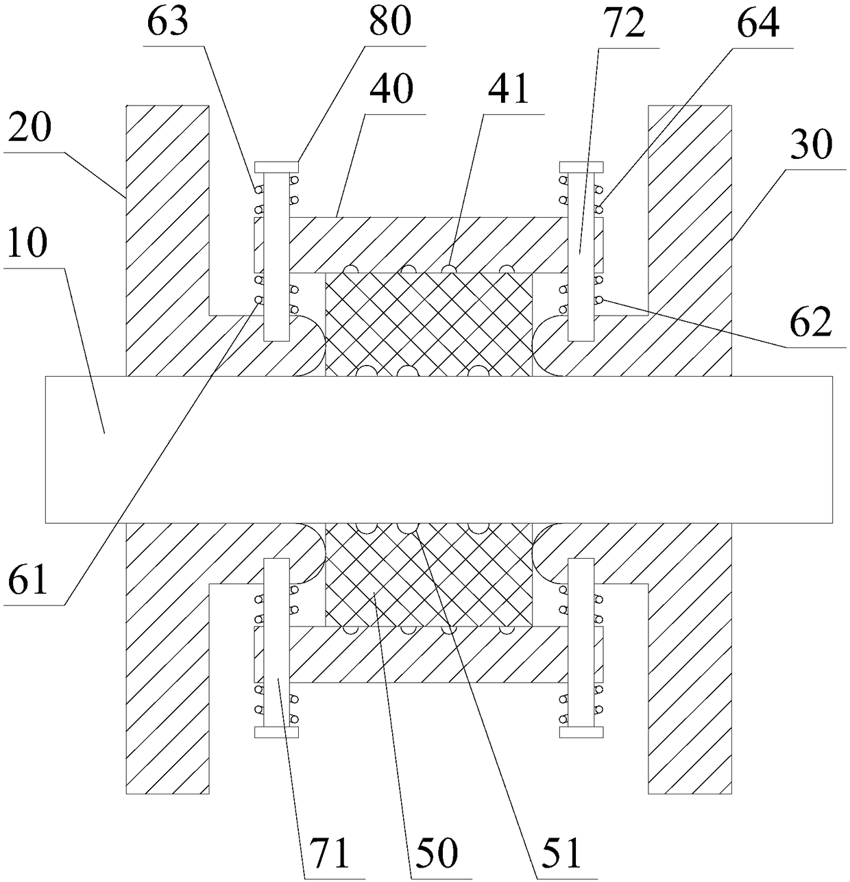
[0030] like figure 1 As shown, the shaft sealing structure for automobiles includes a rotating shaft 10, a left sealing cylinder 20, a right sealing cylinder 30, a middle sealing cylinder 40, a sealing cylinder 50, a first spring 61, a second spring 62, a third spring 63, a Four springs 64, the first fixing bolt 71, the second fixing bolt 72 and the nut 80;

[0031] The middle sealing cylinder 40 is sleeved on the rotating shaft 10, and there is an annular sealing space between the middle sealing cylinder 40 and the rotating shaft 10; the left sealing cylinder 20 and the right sealing cylinder 30 are both sleeved on the rotating shaft 10. On the rotating shaft 10, the left sealing cylinder 20 and the right sealing cylinder 30 are respectively located on the left side and the right side of the middle sealing cylinder 40; one end of the left sealing cylinder 20 and the right sealing cylinder 30 both extend into the In the sealed space; the sealed cylinder 50 is sleeved on the r...

Embodiment 2

[0037] like figure 1 As shown, this embodiment is based on Embodiment 1, and the inner surface of the middle sealing cylinder 40 is provided with a plurality of annular grooves 41 extending around the axis of the rotating shaft 10 .

[0038] An annular groove 41 is provided, and the sealing cylinder 50 is inserted into the annular groove 41 under the action of pressure to increase the sealing performance between the sealing cylinder 50 and the inner surface of the middle sealing cylinder 40 .

Embodiment 3

[0040] like figure 1 As shown, in this embodiment, on the basis of Embodiment 1 or 2, one end face of the left sealing cylinder 20 extending into the sealed space is a protruding arc surface;

[0041] One end surface of the right sealing cylinder 30 extending into the sealed space is a convex arc surface.

[0042] Both the left sealing cylinder 20 and the right sealing cylinder 30 have arc surfaces without sharp corners, so as to prevent the sealing cylinder 50 from breaking due to the sharp corners at the ends of the left sealing cylinder 20 and the right sealing cylinder 30 .


PUM


Abstract

The invention discloses a shaft seal structure for an automobile. The shaft seal device comprises a rotation shaft, a left sealing barrel, a right sealing barrel, a middle sealing barrel, a sealing barrel, a first spring, a second spring, a third spring, a fourth spring, a first fixing bolt, a second fixing bolt and nuts. According to the shaft seal structure, it can be guaranteed that the sealingforce between the sealing barrels on the two sides of the rotation shaft and the rotation shaft is the same, and sealing barrel abrasion due to rotation shaft jumping is avoided. The nuts are used for avoiding large-range sliding of the middle sealing barrel. The first spring, the second spring, the third spring and the fourth spring are used for absorbing part of radial force generated during rotation shaft jumping, and the service life of the sealing barrel is further prolonged. The third spring and the fourth spring can play an anti-loosening role on the nuts. Annular grooves are formed inthe inner surface of the sealing barrel and used for providing the compression allowance when the sealing barrel is compressed, and the sealing barrel is prevented from being pressed and broken.

Description

technical field [0001] The invention relates to a shaft sealing structure for automobiles. Background technique [0002] In the traditional shaft seal structure, packing is set between the sealing cylinder and the rotating shaft, and then the left and right pressure plates are used to extend into the space between the sealing cylinder and the rotating shaft to compress the packing so that the packing is close to the rotating shaft, eliminating the gap between the packing and the rotating shaft. gap, so as to achieve the purpose of sealing. In the traditional shaft seal structure, the sealing cylinder is fixedly connected with the left and right pressure plates, which leads to the fact that when the shaft runs out radially, the shaft will compress the packing on one side, while the packing on the other side of the shaft will become loose , so that the packing is easily worn, which leads to seal failure. Contents of the invention [0003] The object of the present inventio...

Claims


Application Information

Patent Timeline
Patent Type & Authority Applications(China)
IPC IPC(8): F16J15/54
CPCF16J15/54
Inventor 李彬
Owner 重庆乐迪机车车辆配件有限公司
Why Eureka
Try Eureka