Rotational inertia optical measuring method and system

An optical measurement system and moment of inertia technology, used in static/dynamic balance tests, measurement devices, aerodynamic tests, etc., can solve problems such as complex shapes and uneven mass distribution of aircraft, and achieve large amounts of data and use constraints. Fewer, high-fidelity effects

Active Publication Date: 2018-06-26
CHINA ACAD OF AEROSPACE AERODYNAMICS
View PDF12 Cites 9 Cited by
  • Summary
  • Abstract
  • Description
  • Claims
  • Application Information

AI Technical Summary

Problems solved by technology

Objects with regular geometric shapes can use direct calculation or simple equipment to measure their moments of inertia, but for aircraft objects with complex shapes and uneven mass distribution, the moment of inertia can only be measured experimentally

Method used


Image

  • Rotational inertia optical measuring method and system
  • Rotational inertia optical measuring method and system
  • Rotational inertia optical measuring method and system

Examples


Embodiment

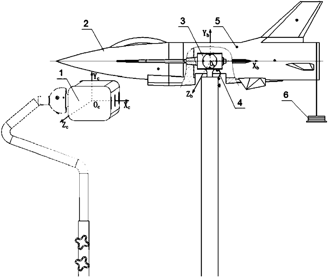
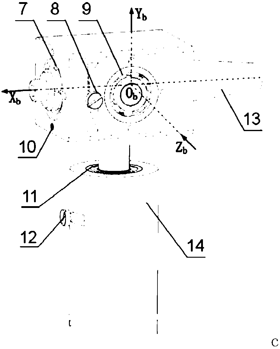
[0039]The aircraft model 2 and the three-degree-of-freedom mechanism 3 are rigidly connected through the model connecting cone 13; taking the current degree of freedom as an example, tighten the roll limit screw 8 and the yaw limit screw 12, and one end of the elastic beam 4 is connected to the current degree of freedom. On the support section 14, the other end is connected to the outer casing of the three-degree-of-freedom mechanism 3 to provide a vibration restoring moment; the marking point 5 is installed on the surface of the aircraft model 2, and the weight loading device 6 is placed at the tail of the aircraft model 2; according to the aircraft model 2 The range of motion during the vibration process, adjust the position and direction of the trinocular vision system 1, to ensure that no less than three identification points 5 are located in the measurement field of view of the trinocular vision system 1 during the vibration process of the aircraft model 1.

[0040] figur...


PUM


Abstract

The invention discloses a rotational inertia optical measuring method and system. The method includes first calculating a transformation matrix between a visual coordinate system and a body axis system with an identification point on an aircraft model as a medium, then utilizing a trinocular vision system to measure the angle change of the model in the body axis system before and after weight loading, calculating the stiffness of an elastic system according to the torque of the weight relative to the center of rotation, exciting the elastic system to perform free vibration after a loading device is removed, measuring an angular displacement curve of the aircraft model during the vibration process in real time to obtain the vibration circular frequency, and repeating the steps for multipletimes to obtain the rotational inertia of the model by using the least square method. By means of the method, measuring efficiency and accuracy of the rotational inertia of the aircraft model in the control response wind tunnel test can be improved.

Description

technical field [0001] The invention relates to an optical measurement method and system for moment of inertia, in particular to optical measurement for model moment of inertia in control response wind tunnel test. Background technique [0002] As a part of the wind tunnel virtual flight test technology, the rudder surface control response wind tunnel test technology can more realistically simulate the aerodynamic change and motion attitude response of the aircraft during motion, and intuitively reflect the stability and stability of the aircraft in the nonlinear range. Controllability, through the coupling characteristics of aerodynamics and flight dynamics, comprehensively predicts the flight performance and flight quality of the aircraft, greatly reducing the risk of flight tests and shortening the development cycle. [0003] The "non-contact" measurement technology based on the principle of stereo vision can realize dynamic instantaneous measurement and spatial three-dim...

Claims


Application Information

Patent Timeline
Patent Type & Authority Applications(China)
IPC IPC(8): G01M1/10G01M9/06
CPCG01M1/10G01M9/06
Inventor 付增良赵俊波梁彬张石玉
Owner CHINA ACAD OF AEROSPACE AERODYNAMICS
Why Eureka
Try Eureka