
Impact wear testing machine

A wear test and support technology, which can be used in testing wear resistance, measuring devices, instruments, etc., to solve the problems of workpiece impact and wear, inability to accurately test workpiece wear and friction coefficient, and small impact load.

Active Publication Date: 2018-06-26
中机试验装备股份有限公司 +1
View PDF12 Cites 1 Cited by
  • Summary
  • Abstract
  • Description
  • Claims
  • Application Information

AI Technical Summary

Problems solved by technology

[0005] At present, there are almost few testing machines that can complete the impact and wear tests at the same time. Usually, the impact and wear tests are carried out on different test equipment; The separate test is obviously not in line with the actual working conditions
In addition, although a small number of testing machines that can perform both impact and abrasion testing actually exist, there are still many problems with this type of testing machine
For example, in the impact test, only rely on the pendulum or eccentric block to load the impact load, the impact load is small, and the operation is cumbersome, making it impossible to accurately test the impact resistance of the workpiece
During the wear test, the given friction conditions of the workpiece are far from the actual working conditions, so parameters such as the wear amount and friction coefficient of the workpiece cannot be accurately tested
[0006] Therefore, the existing testing machine cannot provide test conditions for impact and wear tests that are closer to the actual working conditions for the workpiece to be tested, and the accuracy of the measured mechanical properties of the material is poor.

Method used


Image

  • Impact wear testing machine
  • Impact wear testing machine
  • Impact wear testing machine

Examples


Embodiment Construction

[0062] The following will clearly and completely describe the technical solutions in the embodiments of the present invention with reference to the accompanying drawings in the embodiments of the present invention. Obviously, the described embodiments are only some, not all, embodiments of the present invention. Based on the embodiments of the present invention, all other embodiments obtained by persons of ordinary skill in the art without making creative efforts belong to the protection scope of the present invention.

[0063] In order to enable those skilled in the art to better understand the solution of the present invention, the present invention will be further described in detail below in conjunction with the accompanying drawings and specific embodiments.

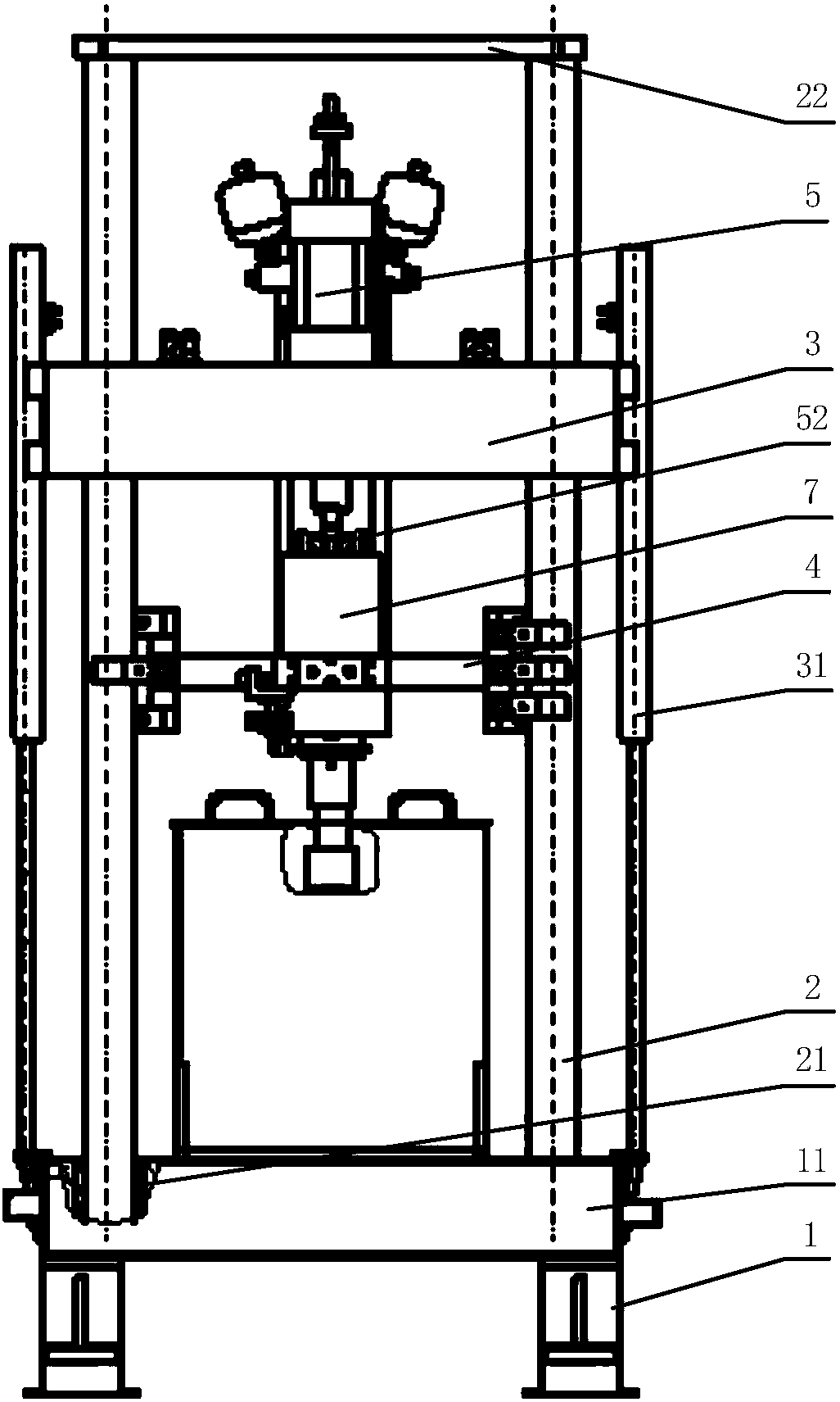
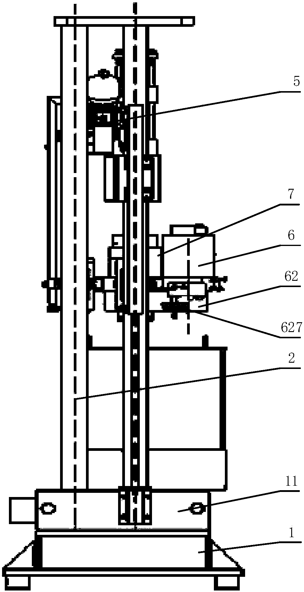
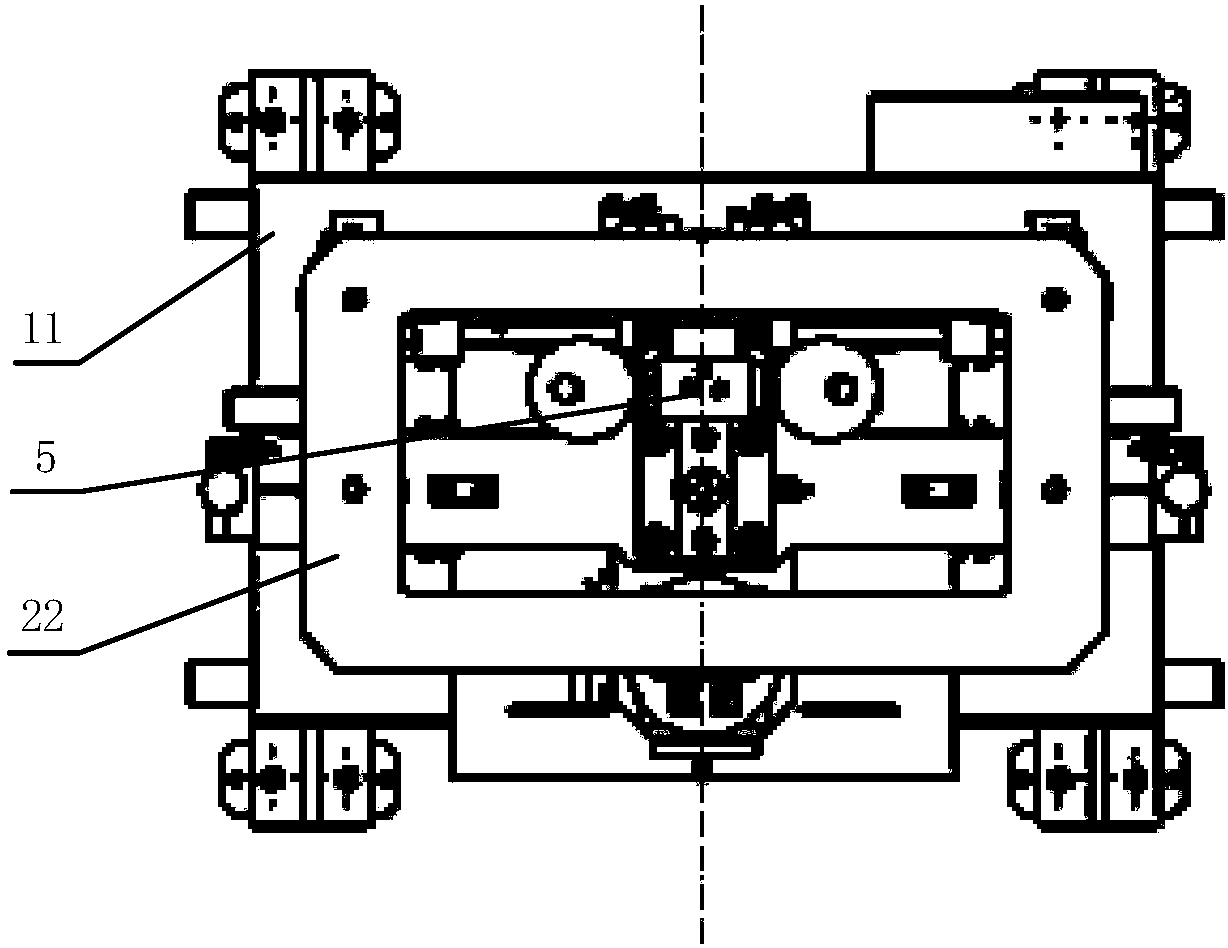
[0064] Please refer to Figure 1 to Figure 3 , figure 1 A schematic front view of the impact wear test provided by a specific embodiment of the present invention; figure 2 for figure 1 side view diagram of ima...


PUM


Abstract

The invention discloses an impact wear testing machine comprising a base (1) and a column (2) and further comprising a first guiding portion (3) mounted on the column (2) and capable of moving longitudinally along the column (2), a second guiding portion (4) connected to the first guiding portion (3), a supporting portion (7) mounted on the second guiding portion (4) and used for supporting a workpiece to be tested, an axial loading portion (5) mounted on the second guiding portion (4) and connected with the top of the supporting portion (7) and a rotating loading portion (6) mounted on the second guiding portion (4) and connected with the side of the supporting portion (7). By application of the testing machine, the axial loading portion (5) and the rotating loading portion (6) can move longitudinally with the first guiding portion (3) and the second guiding portion (4) respectively and simultaneously or independently apply an axial load and a rotational load, test conditions are closer to the actual working conditions, and measured mechanical properties of the material are more accurate.

Description

technical field [0001] The invention relates to the field of testing equipment, in particular to an impact wear testing machine. Background technique [0002] The mechanical properties of the material of the workpiece refer to the ability of the workpiece material to resist deformation or damage under the action of external force, usually including the strength, plasticity, elasticity, brittleness, fracture toughness, hardness and other properties of the material. Generally, in the process of researching and exploring new materials, new processes, new technologies and new structures, it is necessary to use testing machines to measure the material mechanical properties of the workpiece in order to effectively ensure the quality, safety and reliability of the workpiece. Therefore, testing machines are widely used in machinery, metallurgy, aerospace and other industries. [0003] Impact testing is usually used to determine the performance of materials against impact under dyna...

Claims


Application Information

Patent Timeline
IPC IPC(8): G01N3/307G01N3/56
CPCG01N3/307G01N3/56G01N2203/0026G01N2203/0048
Inventor 马伟王澍魏仁杰刘继彬
Owner 中机试验装备股份有限公司
Learn More