Multi-hole tantalum rod device

A technology of porous tantalum and protective tubes, applied in bone implants, joint implants, joint implants, etc., can solve problems such as knocking off tantalum rods, and achieve integrity, stability, and increased firmness Effect

Inactive Publication Date: 2018-06-29
CHONGQING RUNZE PHARM CO LTD
5 Cites 0 Cited by

AI-Extracted Technical Summary

Problems solved by technology

[0003] However, during the implantation process, the tantalum rods need to withstand a large force, and some tantalum rods will be twisted or broken when the bone is finally filled.
At the same time, it ...

Abstract

The invention discloses a multi-hole tantalum rod device which comprises a tantalum rod. The device is characterized by comprising a protective tube for containing the tantalum rod, a concave pit is arranged in the side wall of the protective tube, a conical protrusion is arranged inside the concave pit, the top end of the conical protrusion is flush with the outer surface of the inner wall, and the protective tube is made of rigid elastic materials. A protective frame wraps the tantalum rod, due to the design, it is ensured that the tantalum rod is not broken when embedded into a pre-embeddedhole, and the integrity of the tantalum rod is ensured.

Application Domain

Bone implantJoint implants

Technology Topic

EngineeringTa element +1

Image

  • Multi-hole tantalum rod device
  • Multi-hole tantalum rod device
  • Multi-hole tantalum rod device

Examples

  • Experimental program(1)

Example Embodiment

[0024] The present invention will be further described below in conjunction with the drawings and specific embodiments.
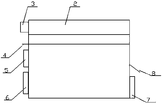
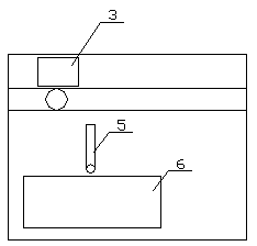
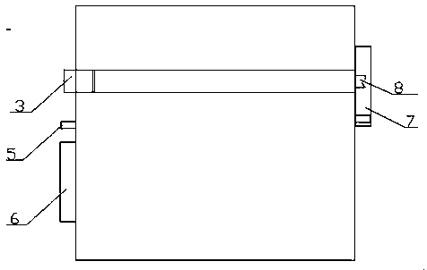
[0025] Such as Figure 1 to Figure 13 As shown, a porous tantalum tantalum rod device includes a tantalum rod 1-1, characterized in that: the tantalum rod device includes a protective tube 1-2 for accommodating the tantalum rod, and the side wall of the protective tube is provided with a recess Holes 1-3, there are conical protrusions 1-4 in the pits, the top of the conical protrusions is level with the outer surface of the inner wall, and the protection tube is made of rigid elastic material.
[0026] When using, put the protective tube into the drilled hole, and then insert the tantalum rod into the protective tube. At this time, the pit on the wall of the protective tube is squeezed by the tantalum rod and bulges outward, and the conical convex inside the pit Press against the inner wall of the borehole to firmly fix the protective tube in the borehole. In this way, the protection tube can protect the tantalum rod from being squeezed, and at the same time, it has better stability with the drilling.
[0027] The porous tantalum tantalum rod device also includes a cleaning device for cleaning the inner tube of the protection tube, wherein the cleaning device includes a base 2 on which a groove for placing the protection tube body is provided, and two side walls of the base are An inlet hole and an outlet hole are respectively provided. The inlet hole and the outlet hole correspond to the two openings of the protective tube body. A pallet 4 is provided on the side wall below the inlet hole, and a pressure cutting device 3 is provided above the inlet hole. , The side wall on the side of the inlet hole is also provided with a rocking rod 5 and a cleaning belt accommodating device 6, and a side wall on the side of the outlet side is provided with a lifting sheet 8 and a trash box 7;
[0028] The cleaning device also includes a cleaning belt, which is provided with wiping fluff, and also has staggered T-shaped heads 10 and blocking knots 11;
[0029] The pressure-cutting device includes a accommodating cavity. A finite piece 3-3 is arranged in the accommodating cavity. A gravity ball 3-1 is vertically arranged in the accommodating cavity. The diameter of the gravity ball matches the diameter of the protective tube body. There is a T-shaped groove running through the sphere, the T-shaped head is matched with the T-shaped groove, the vertical groove of the T-shaped groove is clamped on the limit piece, and a slice 3-2 is provided at the rear of the containing cavity. Two linear motors are arranged on the upper part, and the telescopic rods of the two linear motors are used to press down the gravity ball and control the lifting of the slice respectively; at the bottom of the containing cavity is provided a drop port 9 made of elastic material, The diameter is slightly smaller than the diameter of the gravity ball;
[0030] The bottom of the swing rod is connected to the output shaft of the rotating motor, and the upper part of the swing rod has a square hole;
[0031] The lifting piece is arranged obliquely downward, and the end of the lifting piece is provided with a wedge-shaped opening; the bottom of the lifting piece is stuck in the slide groove of the side wall of the base, and the lifting piece can slide up and down in the slide groove;
[0032] A coil spring is arranged in the cleaning bag containing device, and the end of the cleaning tape is connected with the coil spring and then wound on the coil spring;
[0033] Compressed air inlet holes are also provided at the inlet holes;
[0034] When in use, first place the protective tube into the groove on the base of the cleaning device, so that the two openings of the protective tube are connected to the inlet and outlet on the side wall of the base, and then the cleaning belt is removed from the cleaning belt containing device. Pull it out and place it on the pallet. The single-chip microcomputer controls the linear motor to press down the telescopic rod. The gravity ball at the bottom end is squeezed into the entrance, and the entrance is deformed and expanded, so that when the gravity ball falls, the T-shaped head on the cleaning belt is squeezed Into the T-shaped groove of the gravity ball, and then compressed air into the hole to spray compressed air, pushing the gravity ball to drive the cleaning belt to overcome the tension of the coil spring in the cleaning bag accommodating device and move along the protection tube body. Large gaps or holes, but because the compressed air flow rate is relatively large, and the diameter of the gravity ball is directly matched with the tube body, the gravity ball will move smoothly in the tube body. The single-chip microcomputer controls the swing rod to keep it level and clean. The bag slowly passes through the square hole of the swing rod. When the gravity ball moves to the exit hole, the gravity ball falls out, and the single-chip microcomputer controls the compressed air to stop. Due to the action of gravity, the gravity ball will move downwards and pass the lifting plate. After that, fall into the trash box. The square hole on the rocking rod that is slightly smaller than the resistance junction will jam the resistance junction. Then, the single-chip microcomputer controls the rocking rod to move downwards and the gravity ball is lifted. Since the lifting piece is set tilted down, when the gravity ball moves upward, it will be blocked. The lifting plate is stuck, but at this time, the lifting plate will slide upwards. When the swing lever moves to the bottom end, the lifting plate will move to the top end. Repeatedly, the cleaning belt will move left and right. Such left and right movement will use the cleaning belt. The fluff is used to clean the inside of the tube, and it can be cleaned after several times.
[0035] After cleaning, the swing bar swings to the bottom of its swing range. At this time, the gravity head is stuck in the wedge groove of the lifting plate, the lifting plate rises to the highest point, the entire cleaning belt is tightened, and the single-chip microcomputer controls the linear motor output rod to descend , Press down another gravity ball, the second T-shaped head of the cleaning belt is stuck into the T-shaped groove of the gravity ball, then, the single-chip microcomputer controls the linear motor to lower the slice and cut the cleaning belt, so that the first cleaning belt is due to gravity The role of the cleaning staff falls into the trash box, and the cleaning staff removes the tube body for further disinfection. The swing rod rotates in the reverse direction to make the swing rod to the vertical state with the square hole upward, avoiding the obstruction. If the tube body needs to be automatically cleaned again, the tube body is placed in the groove of the cleaning device, and then the single-chip microcomputer turns on the compressed air to push the gravity The ball passes through the tube, and after the blocking knot leaves the range of the rocking rod, the rocking rod is rotated to the initial horizontal position to wait for the next blocking knot to be blocked, and then the steps described above are repeated for cleaning. Such cleaning of the tube body can be done automatically, which improves the efficiency of cleaning and reduces the time of medical staff.

PUM

no PUM

Description & Claims & Application Information

We can also present the details of the Description, Claims and Application information to help users get a comprehensive understanding of the technical details of the patent, such as background art, summary of invention, brief description of drawings, description of embodiments, and other original content. On the other hand, users can also determine the specific scope of protection of the technology through the list of claims; as well as understand the changes in the life cycle of the technology with the presentation of the patent timeline. Login to view more.

Similar technology patents

Screen capture method and terminal device

InactiveCN108307036ASimplify taking screenshotsIntegrity guaranteed
Owner:VIVO MOBILE COMM CO LTD

Signal testing method

ActiveCN102331530AIntegrity guaranteedEasy resistance matching
Owner:COMAC +1

Classification and recommendation of technical efficacy words

  • Integrity guaranteed
  • Improve firmness

Image acquisition method and image acquisition device

InactiveCN103139480AIntegrity guaranteedImprove photo efficiency
Owner:HUAWEI DEVICE CO LTD

Method, client side and system for broadcasting media fragmentations in turn

InactiveCN103685264AIntegrity guaranteedwaste of processing resources
Owner:LE SHI ZHI XIN ELECTRONICS TECH TIANJIN

Digital value acquisition circuit with fault diagnosis capacity

ActiveCN102916689AImprove self-diagnosis coverageIntegrity guaranteed
Owner:CHINA TECHENERGY +1

Method for safely and flexibly upgrading firmware

InactiveCN103207800AImprove upgrade securityIntegrity guaranteed
Owner:XIAMEN YEALINK NETWORK TECH

High-speed electric connector and signal module thereof, and molding method of signal module

ActiveCN106207569AImprove firmnessSolve easy deformation
Owner:CHINA AVIATION OPTICAL-ELECTRICAL TECH CO LTD

Method for welding aluminum materials

ActiveCN101648312Aadd depthImprove firmness
Owner:KONFOONG MATERIALS INTERNATIONAL CO LTD

Oblique position plumb electric welding method

ActiveCN107042352AImprove firmnessfast flow
Owner:GUANGZHOU SHIPYARD INTERNATIONAL LTD

Environment-friendly PU leather

InactiveCN104372680AGood moisture permeability and air permeabilityImprove firmness
Owner:ZHEJIANG JINSHANG SYNTHETIC LEATHER
Why Eureka
Try Eureka