Cutting device for heat exchange tube of chemical heat exchanger
A technology for cutting devices and heat exchangers, applied in positioning devices, manufacturing tools, metal processing equipment, etc., can solve the problems of complex structure, difficult maintenance, and many parts, and achieve simple structure, low maintenance cost, The effect of low manufacturing cost
- Summary
- Abstract
- Description
- Claims
- Application Information
AI Technical Summary
Problems solved by technology
Method used
Image

Examples
Embodiment 1
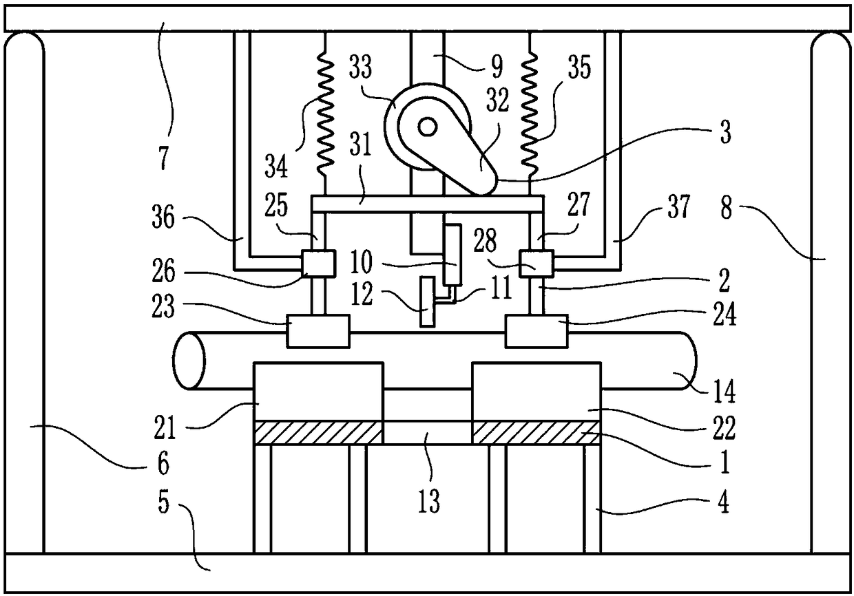
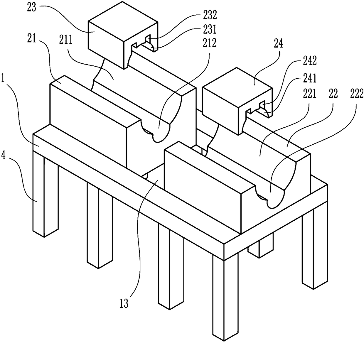
[0027] A cutting device for heat exchange tubes of chemical heat exchangers, such as Figure 1-5 As shown, it includes a workbench 1, a clamping device 2, a driving device 3, a bracket 4, a base 5, a first gantry rod 6, a top plate 7, a second gantry rod 8, a fixing plate 9, a first cylinder 10, a first L-shaped telescopic rod 11 and cutting machine 12; the middle part of the workbench 1 has a blanking opening 13 that penetrates up and down, and a clamping device 2 and a driving device 3 are arranged above the working table 1, and the clamping device 2 is connected with the driving device 3 , the support 4 is located below the workbench 1, the support 4 is connected to the workbench 1 by welding, the support 4 is set to several, the base 5 is located below the support 4, the support 4 and the base 5 are connected by welding, The first gantry bar 6 is located on the left side of the workbench 1, the lower end of the first gantry bar 6 is connected with the left end of the base ...
Embodiment 2
[0029] A cutting device for heat exchange tubes of chemical heat exchangers, such as Figure 1-5 As shown, it includes a workbench 1, a clamping device 2, a driving device 3, a bracket 4, a base 5, a first gantry rod 6, a top plate 7, a second gantry rod 8, a fixing plate 9, a first cylinder 10, a first L-shaped telescopic rod 11 and cutting machine 12; the middle part of the workbench 1 has a blanking opening 13 that penetrates up and down, and a clamping device 2 and a driving device 3 are arranged above the working table 1, and the clamping device 2 is connected with the driving device 3 , the support 4 is located below the workbench 1, the support 4 is connected to the workbench 1 by welding, the support 4 is set to several, the base 5 is located below the support 4, the support 4 and the base 5 are connected by welding, The first gantry bar 6 is located on the left side of the workbench 1, the lower end of the first gantry bar 6 is connected with the left end of the base ...
Embodiment 3
[0032] A cutting device for heat exchange tubes of chemical heat exchangers, such as Figure 1-5 As shown, it includes a workbench 1, a clamping device 2, a driving device 3, a bracket 4, a base 5, a first gantry rod 6, a top plate 7, a second gantry rod 8, a fixing plate 9, a first cylinder 10, a first L-shaped telescopic rod 11 and cutting machine 12; the middle part of the workbench 1 has a blanking opening 13 that penetrates up and down, and a clamping device 2 and a drive device 3 are arranged above the workbench 1, and the clamping device 2 is connected with the drive device 3 , the support 4 is located below the workbench 1, the support 4 is connected to the workbench 1 by welding, the support 4 is set to several, the base 5 is located below the support 4, the support 4 and the base 5 are connected by welding, The first gantry bar 6 is located on the left side of the workbench 1, the lower end of the first gantry bar 6 is connected with the left end of the base 5 top by...
PUM
 Abstract
Description
Claims
Application Information
 - R&D
- Intellectual Property
- Life Sciences
- Materials
- Tech Scout
- Unparalleled Data Quality
- Higher Quality Content
- 60% Fewer Hallucinations
Browse by: Latest US Patents, China's latest patents, Technical Efficacy Thesaurus, Application Domain, Technology Topic, Popular Technical Reports.
© 2025 PatSnap. All rights reserved.Legal|Privacy policy|Modern Slavery Act Transparency Statement|Sitemap|About US| Contact US: help@patsnap.com