Working table for display panel testing

A technology for display panels and workbenches, which is applied to workbenches, manufacturing tools, optical test defects/defects, etc., can solve the problems of increased maintenance personnel, increased floor space, increased equipment cost investment, etc., to reduce detection costs and reduce The effect of equipment investment

Active Publication Date: 2018-06-29
BOE TECH GRP CO LTD +1
View PDF16 Cites 2 Cited by
  • Summary
  • Abstract
  • Description
  • Claims
  • Application Information

AI Technical Summary

Problems solved by technology

Since the AOI mode is for camera shooting, if the distance between the display panel and the polarizer is relatively close during detection, the foreign matter such as dust on the polarizer will be clearly captured by the camera within the focal length range, and it will be mistaken as bad. Therefore, in AOI mode , the distance between the display panel and the polarizer is larger
In the manual detection mode, if the distance between the display panel and the polarizer is large, the environment between the display panel and the polarizer will affect the detection
[0004] Due to the different requirements of manual inspection and automatic optical inspection, the corresponding workbenches for display panel inspection are also divided into two different structures, which cannot be shared, which makes it impossible to perform manual inspection and automatic optical inspection on the same lighting inspection equipment. Switching, therefore, the workbench that currently adopts manual inspection and automatic optical inspection is used separately
However, due to the immature AOI technology at present, manual inspection and automatic optical inspection are required for the mixed use of display panel inspection. This requires the configuration of lighting inspection equipment with manual inspection workbench and lighting inspection equipment with automatic optical inspection workbench. Increased investment in equipment costs. At the same time, the increase in equipment leads to an increase in maintenance personnel and an increase in floor space, which also increases cost input.

Method used


Image

  • Working table for display panel testing
  • Working table for display panel testing
  • Working table for display panel testing

Examples


Embodiment Construction

[0025] The workbench for display panel inspection of the present invention will be described in further detail below in conjunction with the accompanying drawings, but it is not intended to limit the present invention.

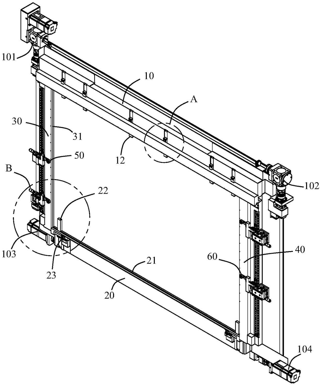
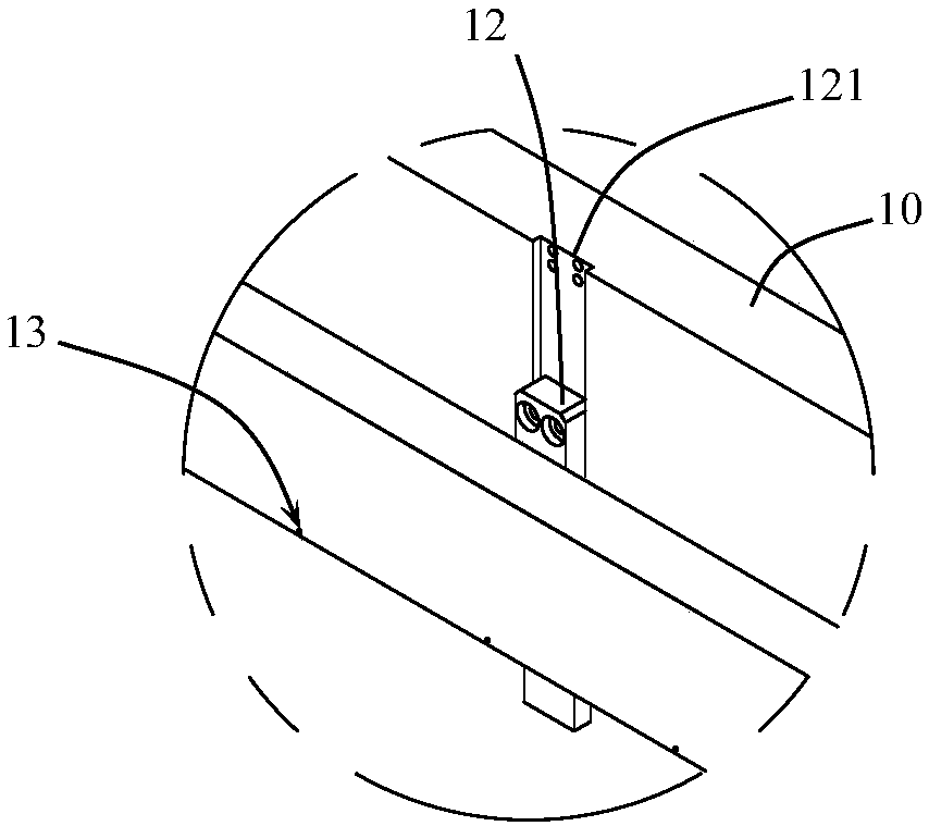
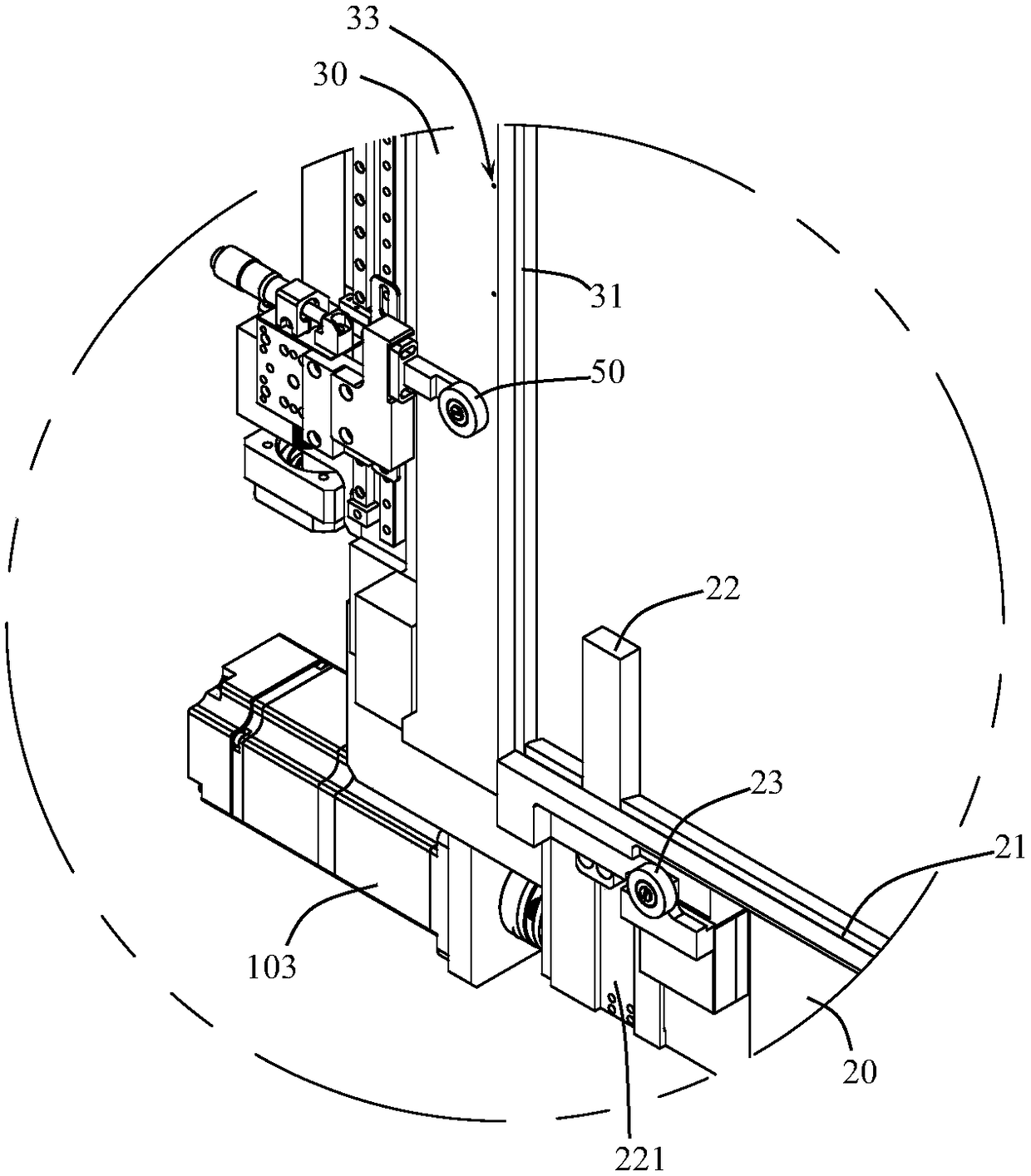
[0026] see Figure 1-8 , the display panel detection workbench according to the embodiment of the present invention includes an upper support block 10, a lower support block 20, a left support block 30 and a right support block 40 for fixing a display panel 100 to be detected, and the upper support block 10 and the distance between the lower support block 20 is adjustable, the distance between the left support block 30 and the right support block 40 is adjustable, by adjusting the distance between the upper support block 10 and the lower support block 20 and the The distance between the left support block 30 and the right support block 40 can adapt to the detection of display panels 100 of different sizes.

[0027] Described upper support block 10, lower supp...


PUM


Abstract

The invention discloses a working table for display panel testing. The working table comprises an upper supporting block, a lower supporting block, a left supporting block and a right supporting blockwhich are used for fixing a display panel to be detected. The distance between the upper supporting block and the lower supporting block is adjustable. The distance between the left supporting blockand the right supporting block is adjustable. The upper supporting block, the lower supporting block, the left supporting block and the right supporting block define a light transmitting space. The upper supporting block, the lower supporting block, the left supporting block and the right supporting block are provided with fixing parts used for fixing a polarizing plate to the light transmitting space. The working table for display panel testing is adopted for both manual detection and automatic optical detection. Input of equipment is reduced, and the detection cost is lowered.

Description

technical field [0001] The invention relates to the technical field of display panels; in particular, the invention relates to a workbench for display panel testing. Background technique [0002] During the manufacturing process of the display panel, multiple inspection procedures need to be carried out, and one of the most important inspection procedures is the lighting inspection to determine whether the display panel is defective. [0003] The workbench for lighting detection is the part of the lighting detection equipment that carries the display panel, and the display panel is lit on the workbench with a signal to detect whether there is a defect on the display panel. At present, the lighting inspection modes in the industry are manual inspection mode and automatic optical inspection (AOI: AutoOptics Inspection) mode. Since the AOI mode is for camera shooting, if the distance between the display panel and the polarizer is relatively close during detection, foreign obje...

Claims


Application Information

Patent Timeline
IPC IPC(8): B25H1/00G01N21/88
CPCB25H1/00G01N21/88
Inventor 谢宗添郭宏雁郑尧燮于洋钟贵平吴怀亮王勇蒋增杨汤存对姚华忠王靖钰
Owner BOE TECH GRP CO LTD
Why Eureka
Try Eureka