
Transverse cutting mechanism

A technology of cross-cutting and cutting knife, which is applied in the direction of metal processing, cardboard articles, etc., which can solve the problems of affecting the stability of the equipment, affecting the cutting quality, and low cutting efficiency, and achieves small vibration, good cutting quality, and high-speed cutting. cut effect

Pending Publication Date: 2018-06-29
启东市美迅机械有限公司
View PDF1 Cites 3 Cited by
  • Summary
  • Abstract
  • Description
  • Claims
  • Application Information

AI Technical Summary

Problems solved by technology

There are two problems in the existing cross-cutting device. 1. The upper knife uses a crank-link mechanism to perform repeated cutting actions. High-speed cutting will cause the knife holder to vibrate, which will affect the stability of the equipment and also affect the cutting quality; 2. The upper knife moves up and down once to realize cutting once. When cutting, the feeding stops, and then feeding is carried out after cutting. It is intermittent feeding, and the efficiency of feeding and cutting is low.

Method used


Image

  • Transverse cutting mechanism
  • Transverse cutting mechanism

Examples


Embodiment 2

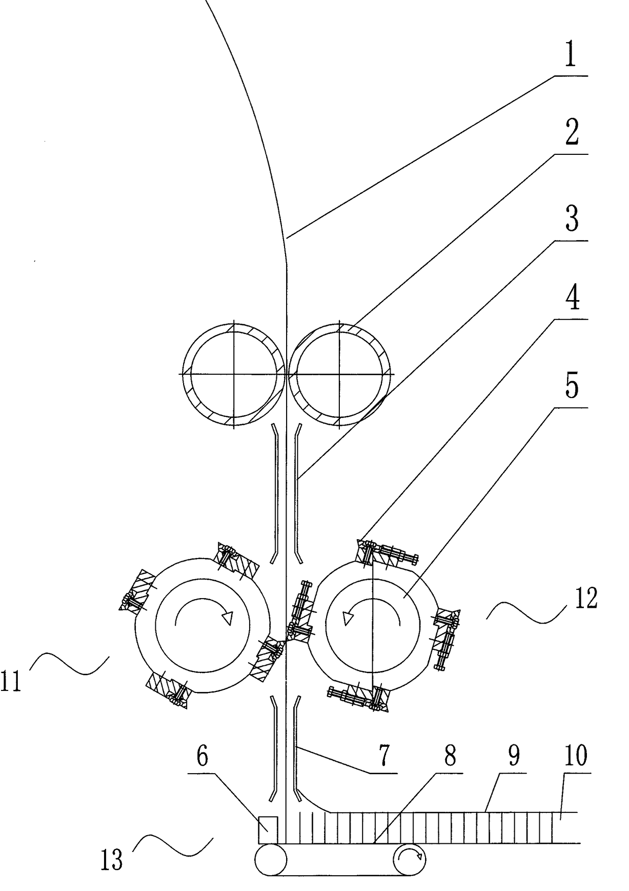
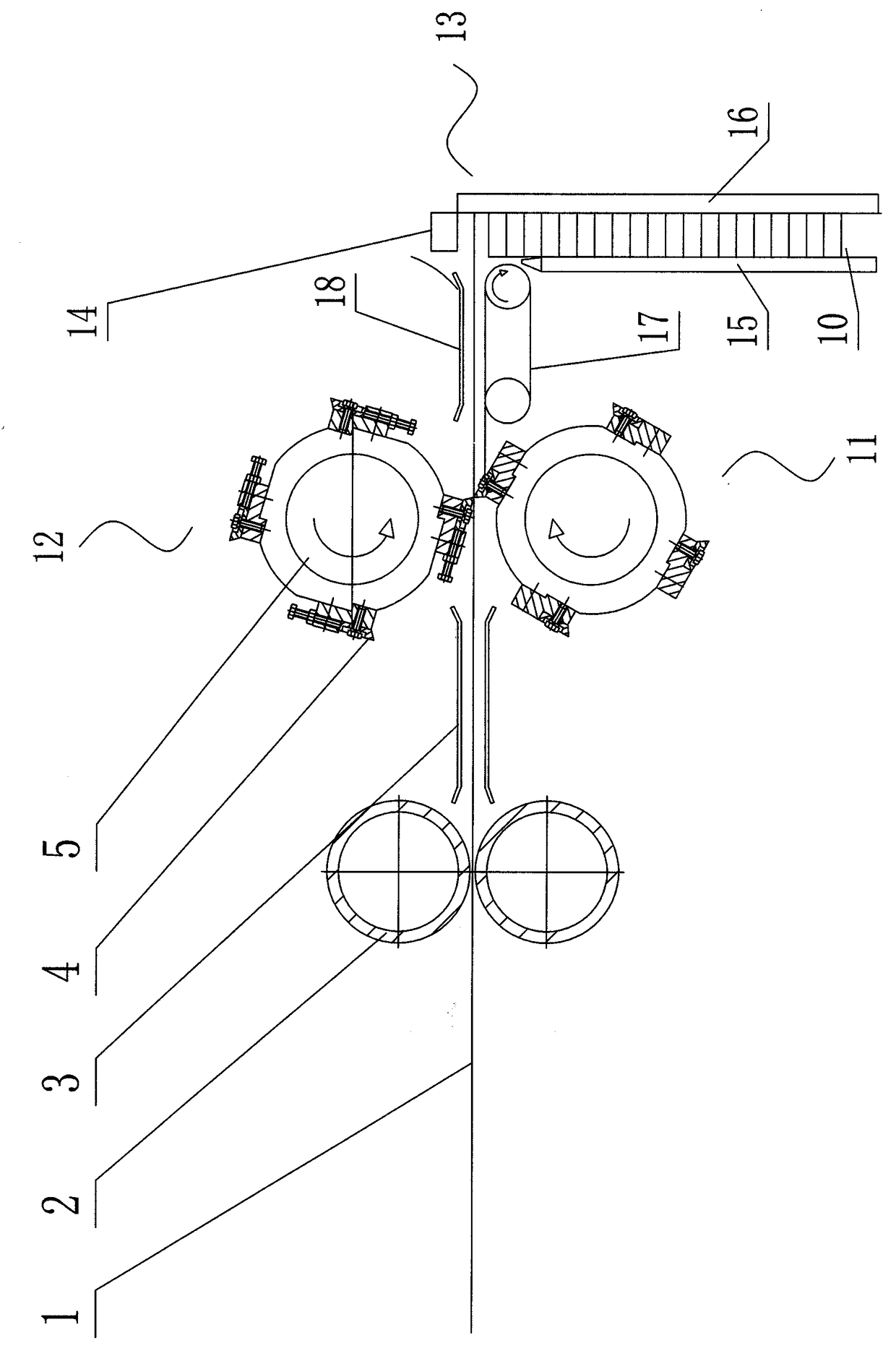
[0019] Embodiment two, adopt horizontal arrangement, refer to figure 2 , the feeding roller 2 and the paper core stacking composite part 13 are respectively arranged on both sides of the roller cutter group, the feeding roller 2 includes an upper roller and a lower roller arranged up and down, and the paper core stacking composite part 13 includes Vertically arranged stacking channel 10 and horizontally arranged conveyor belt 17, the stacking channel 10 is formed by a left baffle 15 and a right baffle 16, and the distance between the left baffle and the right baffle is the same as that of the paper core strip. The lengths are matched, and a briquetting block 14 is arranged above the stacking channel, and the briquetting block 14 is connected to a power source that drives it to lift. The power source can be a cylinder or a mechanical lift. A paper core strip deflector 18 is provided, and the paper core strip deflector 18 guides the cut paper core strip onto the conveyor belt 1...


PUM


Abstract

The invention discloses a transverse cutting mechanism. The transverse cutting mechanism comprises feeding rollers, and is characterized in that the transverse cutting mechanism further comprises a rolling cutter set and a paper core stacking composite component, wherein the rolling cutter set comprises a rolling cutter I and a rolling cutter II which are matched with each other, the rolling cutter I and the rolling cutter II correspondingly comprise rotating shafts and cutters arranged on the rotating shafts; at least two pairs of cutters are arranged on the rotating shafts, and the cutters are uniformly installed on the rotating shafts in the circumferential direction of the cutters, the numbers of the cutters of the rolling cutter I and the rolling cutter II are the same and are arranged in a one-to-one correspondence mode. According to the transverse cutting mechanism, the rolling cutter set is adopted for cutting, the conveying of the paper core plate cannot be influenced during cutting, the paper core plate is enabled to be kept at a high-speed conveying state; and moreover, rolling cutting vibration is small, the stability is high, and the cutting quality is good.

Description

technical field [0001] The invention relates to an improved invention of a cross-cutting mechanism, in particular to a cross-cutting mechanism of a honeycomb paper core of a honeycomb paperboard machine. Background technique [0002] After the multi-layer core paper is compounded into a core board, it is cut into core strips by a cross-cutting mechanism, and the core strips are compounded into a continuous honeycomb paper core. The traditional cross-cutting mechanism adopts horizontal conveying and longitudinal cutting. Please refer to the Chinese patent, the patent number is 201320826424.4, and the invention patent is "A Cross-cutting Device for Honeycomb Paper Core". The paper core board in the above patent is conveyed horizontally. Cutting is realized by the cooperation of the upper knife and the lower knife. There are two problems in the existing cross-cutting device. 1. The upper knife uses a crank-link mechanism to perform repeated cutting actions. High-speed cutting ...

Claims


Application Information

Patent Timeline
Patent Type & Authority Applications(China)
IPC IPC(8): B26D1/36B26D1/40B26D7/06B26D7/32B31D3/02
CPCB26D1/365B26D1/405B26D7/0675B26D7/32B26D2007/322B31D3/0223
Inventor 王文中应树丰应海全应海舟
Owner 启东市美迅机械有限公司
Learn More