Household intelligent cutting machine
A shredding machine and intelligent technology, applied in metal processing and other directions, can solve the problems of low safety and slow shredding speed of potato shreds, and achieve the effects of compact and reasonable structure, time saving and high safety in use.
- Summary
- Abstract
- Description
- Claims
- Application Information
AI Technical Summary
Problems solved by technology
Method used
Image
Examples
Embodiment 1
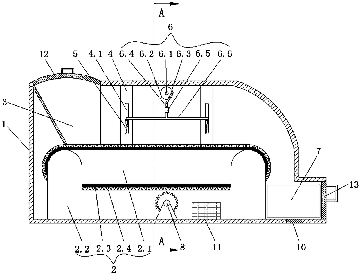
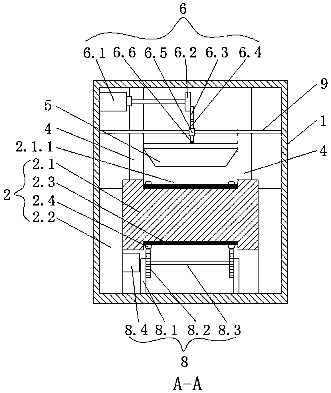
[0026] Such as Figures 1 to 2 As shown, this embodiment provides a household intelligent shredding machine, including a casing 1, and a conveying device 2 for conveying potatoes is arranged in the casing 1. The left end of the conveying device 2 is the feeding end, and the right end of the conveying device 2 is the discharging end. At the end of the casing 1, there is a feed bin 3 located at the feed end. On the right side of the feed bin 3, there are two sets of guide sliding mechanisms in the conveying direction of the conveying device 2. Each set of guide slide mechanisms includes a The guide slide plates 4 at the front and rear ends of the device 2 are provided with guide slide grooves 4.1 on the guide slide plate 4, and blades 5 are arranged between the corresponding two guide slide grooves 4.1, and a blade 5 is arranged in the casing 1 to drive two blades 5 up and down at the same time. The driving mechanism 6 of the movement is provided with a collecting box 7 for rece...
Embodiment 2
[0029] Such as Figures 1 to 2 As shown, this embodiment is further optimized on the basis of Embodiment 1. Specifically, the conveying device 2 includes a conveying platform 2.1, and the conveying platform 2.1 is connected with a number of support columns 2.2 fixed on the inner bottom of the casing 1. The surface of the conveyor table 2.1 is provided with a circle of grooves 2.1.1, the groove 2.1.1 is provided with a conveyor belt 2.3 below the blade 5, and the groove 2.1.1 is provided with two belts for driving the conveyor belt 2.3 to slide. Chain 2.4, the two chains 2.4 are respectively located on the two sides of the conveyor belt 2.3, the bottom of the casing 1 is provided with a transmission mechanism 8 that drives the rotation of the two chains 2.4, the transmission mechanism 8 includes two hinges fixed on the bottom of the casing 1 Seat 8.1, the sprockets 8.2 meshing with the corresponding chain 2.4 are movable on the two hinge seats 8.1, the rotating shaft 8.3 is con...
Embodiment 3
[0032] Such as Figures 1 to 2As shown, this embodiment is further optimized on the basis of Embodiment 1. Specifically, the drive mechanism 6 includes a drive motor 6.1 fixed on the inner wall of the casing 1, and the output shaft of the drive motor 6.1 is connected to a The runner 6.2 in the middle of the two groups of slide guide mechanisms, the edge of the runner 6.2 is movably connected with the first connecting rod 6.3, the first connecting rod 6.3 is movably connected with the second connecting rod 6.4, and the second connecting rod 6.4 is set with a vertical The limit sleeve 6.5, the two ends of the limit sleeve 6.5 are connected with the fixed rod 9 fixed on the inner wall of the casing 1, the bottom of the second connecting rod 6.4 is vertically connected with the third connecting rod 6.6 below the limit sleeve 6.5, The two ends of the third connecting rod 6.6 are respectively connected to the centers of the tops of the two blades 5 .
[0033] In this embodiment, wh...
PUM
 Abstract
Description
Claims
Application Information
 - R&D
- Intellectual Property
- Life Sciences
- Materials
- Tech Scout
- Unparalleled Data Quality
- Higher Quality Content
- 60% Fewer Hallucinations
Browse by: Latest US Patents, China's latest patents, Technical Efficacy Thesaurus, Application Domain, Technology Topic, Popular Technical Reports.
© 2025 PatSnap. All rights reserved.Legal|Privacy policy|Modern Slavery Act Transparency Statement|Sitemap|About US| Contact US: help@patsnap.com


