Regenerative braking energy feedback system

An energy feedback, regenerative braking technology, applied in electric braking systems, electric vehicles, power management, etc., can solve the problems of high cost, increased volume and cost, and large occupation

Active Publication Date: 2018-06-29
NINGBO JIANGBEI GOFRONT HERONG ELECTRIC
View PDF4 Cites 2 Cited by
  • Summary
  • Abstract
  • Description
  • Claims
  • Application Information

AI Technical Summary

Problems solved by technology

[0002] Now the subway in most cities is one of the means of transportation for human travel. Due to the frequent braking of the subway, the power amplitude of the regenerative braking energy is large. The traditional energy storage method requires the energy storage unit to have a large power and capacity, resulting in a large volume And the cost incre

Method used


Image

  • Regenerative braking energy feedback system
  • Regenerative braking energy feedback system
  • Regenerative braking energy feedback system

Examples


Embodiment

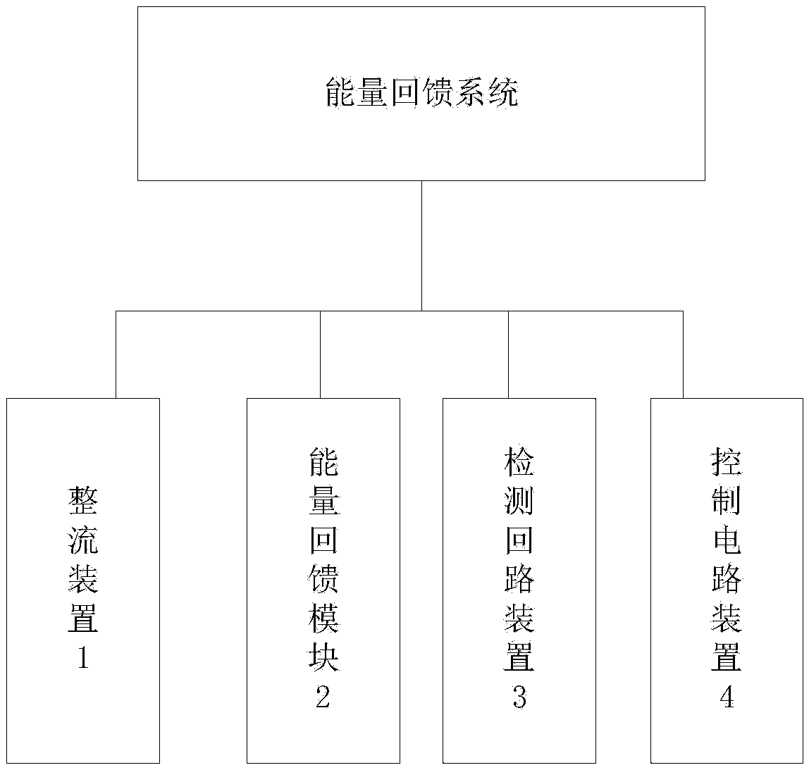
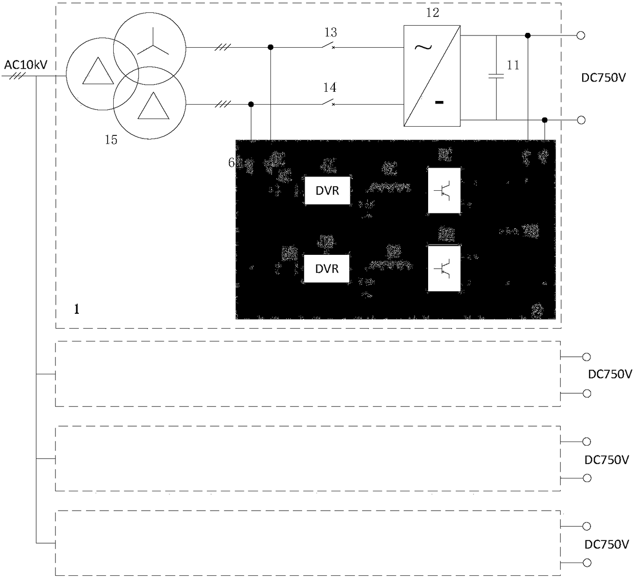
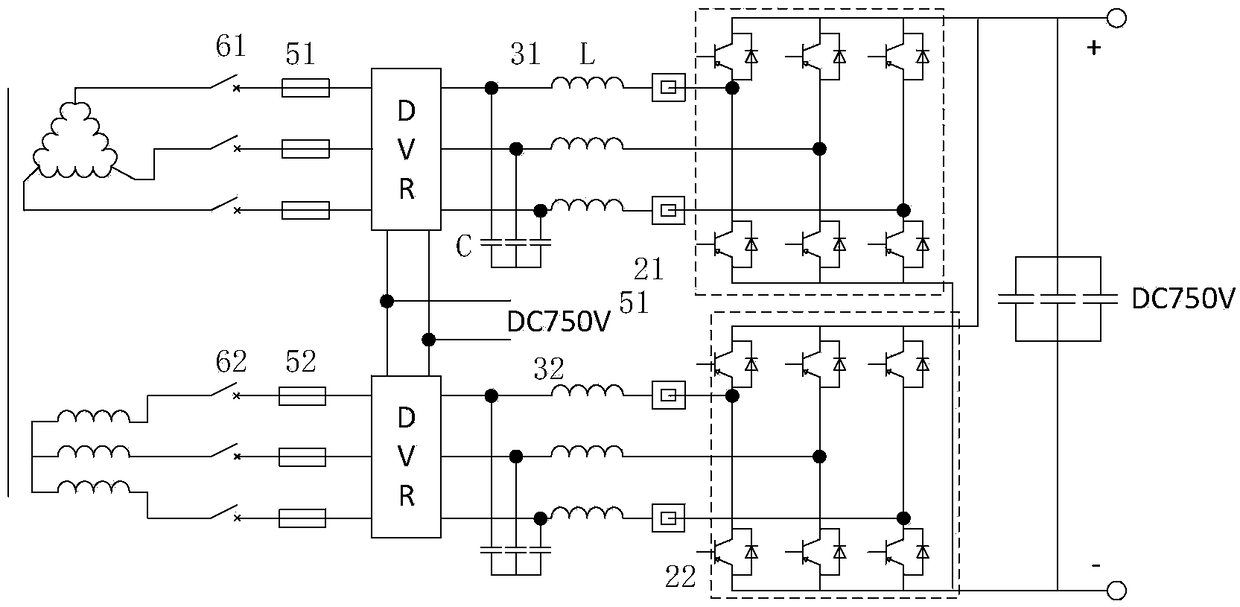
[0073] Such as figure 1 , 2 and 3, a regenerative braking energy feedback system, including the original diode rectifier device 1, energy feedback module 2, detection circuit device 3, control circuit device 4. A set of energy feedback modules 2 are connected in anti-parallel to each of the original diode rectifier devices. The energy feedback modules 2 are also connected to a detection loop device 3, and the detection loop device 3 is also connected to a control circuit device 4.

[0074] According to the three-mode operation of the rectifier power supply system: DC750V / 3MW, DC1500V / 6MW and DC3000V / 9MW, the maximum DC current is 5kA, and the maximum power of the feedback is also 9MW. Set the number of different groups and the connection mode of the device: when DC750V / 3MW When two groups of rectifier devices are connected in parallel, the DC power supply current is 3MW / 750V=4kA, and each set of current is 2kA; when DC1500V / 6MW, two groups of rectifier devices are connected in se...


PUM


Abstract

The invention discloses a regenerative braking energy feedback system. The system comprises diode rectifiers, energy feedback modules, detection loop devices and control circuit devices, a group of energy feedback modules are connected with a group of diode rectifiers in anti-parallel, the energy feedback modules are connected with the detection loop devices, and the detection loop devices are also connected with the control circuit devices. The system can leave out an additional boost transformer for controlling braking energy, effectively reduce cost, reduce energy waste, and improve environmental protection quality.

Description

Technical field [0001] The present invention relates to the field of urban rail transit power supply devices, in particular to a regenerative braking energy feedback system. Background technique [0002] Nowadays, subways in most cities are one of the means of human travel. Due to the frequent braking of subways, the power of regenerative braking energy is large. The traditional energy storage method requires the energy storage unit to have large power and capacity, resulting in large volume. Cost increases, and too frequent charging and discharging will affect the life of the energy storage unit. In order to solve the above technical problems, the existing technology requires an additional step-up transformer to complete the return after the regenerative braking energy is converted. Task, but its cost is high and takes up a lot of space. [0003] In view of the foregoing defects, the creator of the present invention finally obtained the present invention after a long period of re...

Claims


Application Information

Patent Timeline
IPC IPC(8): B60L7/16B60M3/00H02J3/38H02M7/797H02M1/12
CPCB60L7/16B60L2210/40B60M3/00H02J3/38H02M1/126H02M7/797Y02T10/72
Inventor 洪光毛元奇詹娜
Owner NINGBO JIANGBEI GOFRONT HERONG ELECTRIC
Why Eureka
Try Eureka