Packing box and method for thin film solar cells

A technology of solar cells and packaging methods, applied in the field of solar cells, capable of solving problems such as bumping and shaking of thin-film solar cells, power attenuation of thin-film solar cells, failure of thin-film solar cells, etc., achieving a convenient packaging method, simple structure, and easy industrial production Effect

Inactive Publication Date: 2018-06-29
CNBM CHENGDU OPTOELECTRONICS MATERIAL
View PDF5 Cites 4 Cited by
  • Summary
  • Abstract
  • Description
  • Claims
  • Application Information

AI Technical Summary

Problems solved by technology

[0003] In the commercial production process, the existing thin-film solar cell packaging devices use ordinary packing boxes. The transportation process also produced a large number of cracked modules, especially for the long-distance transportation distance and the unevenness of the transportation road, which caused the thin-film solar cells to be in a state of bumping and shaking for a long time, and the thin-film solar cells in the box were squeezed and touched each other, causing Thin-film solar cells produce a large number of newly added cracks, and in the later stage, a large number of cell failure areas are formed in the environmental processes of wind pressure, snow pressure, and cold and heat cycles, resulting in a large power attenuation of thin-film solar cells and hot spot effects of components, resulting in Thin-film solar cells fail

Method used


Image

  • Packing box and method for thin film solar cells
  • Packing box and method for thin film solar cells
  • Packing box and method for thin film solar cells

Examples


Embodiment 1

[0050] Such as Figure 1-8 Shown:

[0051] A packaging box for thin-film solar cells, comprising:

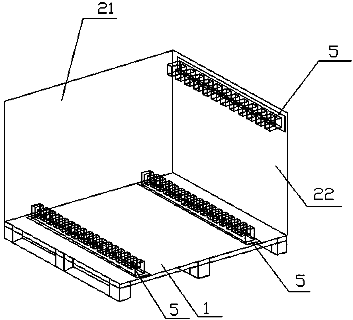
[0052] Tray 1, used to carry thin-film solar cells;

[0053]The outer shroud 2 is arranged on the outer side of the tray 1; the rear side of the outer shroud 2 includes: a vertically arranged first limiting plate 21 and a first side panel 23, and the first limiting plate 21 is set On the lower part of the first side panel 23; the right side of the outer wall 2 includes: a vertically arranged second limiting plate 22 and a second side panel 24, the second limiting plate 22 is arranged on the second side The lower part of the panel 24; the left side of the outer coaming board 2 is: the third side panel 25 arranged vertically; the front side of the outer coaming board 2 is: the fourth side panel 26 arranged vertically;

[0054] The box cover 3 is arranged on the top of the outer coaming plate 2;

[0055] Corner guards 4 are arranged at the corners of the outer panel 2;

[0056...

Embodiment 2

[0068] The difference between this embodiment and Embodiment 1 is that the limiting slot 5 and the protective slot 6 are elongated structures; the limiting slot 5 has a groove running through its width direction; The protection card slot 6 has a groove running through its width direction.

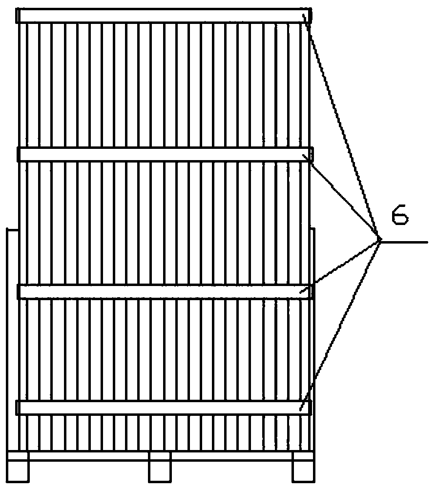
[0069] The protective card slot 6 is multi-layer corrugated cardboard; the protective card slot 6 is foamed PE. The first limiting plate 21 and the second limiting plate 22 are plywood. The first side panel 23, the second side panel 24, the third side panel 25 and the fourth side panel 26 are honeycomb paperboard. The corner guard 4 is a paper corner guard 4 .

[0070] The limiting slot 5 is adhesively connected to the upper part of the tray 1 and the left side of the second limiting plate 22 . Described protection draw-in groove 6, paste is connected in described case cover 3 bottoms, described second side panel 24 left side and described 3rd side panel 25 right sides. The pasting conn...

Embodiment 3

[0073] The only difference between this embodiment and embodiment 1 is that

[0074] A packaging method for thin film solar cells, comprising:

[0075] A) provide a pallet 1, the rear side of the pallet 1 is vertically provided with a first limiting plate 21, and the right side of the pallet 1 is vertically provided with a second limiting plate 22; The left side of the two limiting plates 22 is pasted and connected to the limiting card slot 5 .

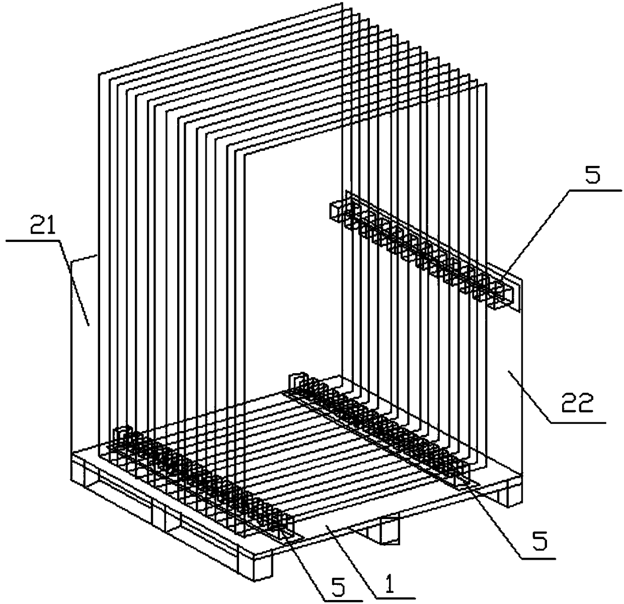
[0076] B1) placing a plurality of thin film solar cells vertically on the tray 1 in turn;

[0077] B2) The lower right side and the bottom end of the thin film solar cell are engaged and fixed through the groove of the limit card slot 5; the limit card slot 5 is an elongated structure; the limit card slot 5 has a groove running through its width;

[0078] C) Engage and fix the left side, the upper end, and the upper right side of the thin film solar cell through the groove of the protection card slot 6; the protection card slot 6 i...


PUM


Abstract

The invention discloses a packing box and method for thin film solar cells. The packing box comprises a tray, an external fence plate, a box cover, corner protectors, limiting slots and protecting slots, wherein the external fence plate is arranged on the outer side of the periphery of the tray; the rear side of the external fence plate comprises a first limiting plate and a first side panel whichare arranged vertically; the first limiting plate is arranged on the lower portion of the first side panel; the right side of the external fence plate comprises a second limiting plate and a second side panel which are arranged vertically; the second limiting plate is arranged on the lower portion of the second side panel; the left side of the external fence plate comprises a third side panel which is arranged vertically; the front side of the external fence plate comprises a fourth side panel which is arranged vertically; the limiting slots are formed in the upper portion of the tray and theleft side of the second limiting plate; and the protecting slots are formed in the lower portion of the box cover, the left side of the second side panel and the right side of the third side panel. By the packing box and method, the circumstance that the thin film solar cells are jolted and shake in a transportation process and are extruded to one another and in contact with one another can be avoided effectively.

Description

technical field [0001] The invention relates to the technical field of solar cells, in particular to a packaging box and a packaging method for thin-film solar cells. Background technique [0002] Solar energy is a clean, efficient and inexhaustible new energy source, and it is one of the important renewable energy sources. The research direction of solar energy is high conversion efficiency, low cost and high stability. Therefore, thin-film solar cells with high conversion efficiency, low cost and high stability have attracted much attention. Thin-film solar cells are easy to manufacture and their commercialization is developing rapidly. [0003] In the commercial production process, the existing thin-film solar cell packaging devices use ordinary packing boxes. The transportation process also produced a large number of cracked modules, especially for the long-distance transportation distance and the unevenness of the transportation road, which caused the thin-film solar ...

Claims


Application Information

Patent Timeline
Patent Type & Authority Applications(China)
IPC IPC(8): B65D19/44B65D85/88
CPCB65D19/44B65D85/70B65D2519/0082B65D2585/88
Inventor 彭寿马立云潘锦功殷新建孙庆华
Owner CNBM CHENGDU OPTOELECTRONICS MATERIAL
Why Eureka
Try Eureka