Air-floatation oil removal tank for treating oil-containing waste water and oil removal method

A technology for air flotation and wastewater, which is applied in the direction of grease/oily substance/suspton removal device, separation method, flotation water/sewage treatment, etc., which can solve the problem of affecting the treatment process and cannot fully separate oily wastewater and wastewater containing dissolved oil. Deal with problems such as unsatisfactory results, and achieve full separation and degreasing effects

Pending Publication Date: 2018-06-29
山东纯江环境科技有限公司
View PDF2 Cites 0 Cited by
  • Summary
  • Abstract
  • Description
  • Claims
  • Application Information

AI Technical Summary

Problems solved by technology

[0002] At present, for the removal of dissolved oil in oily wastewater from metallurgical industry and chemical industry, the treatment process of general oil removal equipment is relatively simple, and the treatment effect on wastewater containing dissolved oil is not ideal, and the oil in oily wastewater cannot be fully separated, and subsequent treatment is affected craft

Method used


Image

  • Air-floatation oil removal tank for treating oil-containing waste water and oil removal method

Examples


Embodiment Construction

[0023] The technical scheme of the present invention is described in detail below in conjunction with accompanying drawing:

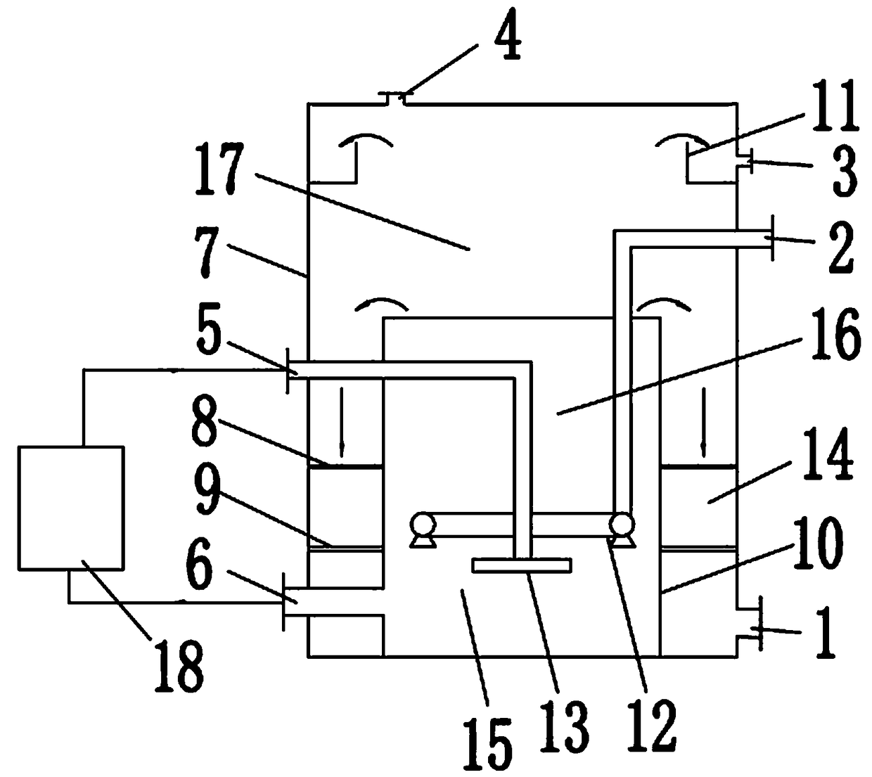
[0024] Such as figure 1 , an air flotation degreasing tank for treating oily wastewater, comprising a tank body 7, the upper part of the inner cavity of the tank body 7 is a separation zone 17, and the lower part of the inner cavity of the tank body 7 is vertically provided with a cylindrical partition 10, the partition The plate 10 divides the lower part of the inner cavity of the tank body 7 into a central air flotation area and a peripheral water outlet area; the tops of the air flotation area and the water outlet area communicate with the separation area 17;

[0025] The top of the tank body 7 is provided with an exhaust port 4;

[0026] The top of the tank body 7 is provided with an oil outlet 3, and the inner side of the oil outlet 3 is provided with an oil outlet weir 11;

[0027] The bottom of the tank body 7 is provided with a water outlet 1 ...


PUM


Abstract

The invention discloses an air-floatation oil removal tank for treating oil-containing waste water and an oil removal method. The air-floatation oil removal tank comprises a tank body, wherein the upper part of an inner cavity of the tank body is a separation area, the lower part of the inner cavity of the tank body is vertically provided with a separation plate, and the lower part of the inner cavity of the tank body is divided by the separation plate into an air floatation area and a water outlet area; the tops of the air floatation area and the water outlet area are respectively communicated with the separation area; the top of the tank body is provided with an air outlet; the top of the tank body is provided with an oil outlet; the bottom of the tank body is provided with a water outlet communicated with the water outlet area; the tank body is also provided with a water inlet for transporting waste water to be treated to the air floatation area; and the air-floatation oil removal tank comprises an air transport apparatus for transporting gas to the air floatation area. By adopting the air-floatation oil removal tank, the oil removal effect can be improved, and the oil in the oil-containing waste water can be sufficiently separated.

Description

technical field [0001] The invention relates to an air flotation degreasing tank for treating oily waste water, and also relates to an air flotation degreasing method, which belongs to the technical field of oily waste water treatment. Background technique [0002] At present, for the removal of dissolved oil in oily wastewater from metallurgical industry and chemical industry, the treatment process of general oil removal equipment is relatively simple, and the treatment effect on wastewater containing dissolved oil is not ideal, and the oil in oily wastewater cannot be fully separated, and subsequent treatment is affected craft. Contents of the invention [0003] The invention proposes an air flotation deoiling tank and a degreasing method for treating oily waste water, the purpose of which is to improve the degreasing effect and fully separate the oil in the oily waste water. [0004] Technical scheme of the present invention is as follows: [0005] An air flotation an...

Claims


Application Information

Patent Timeline
Patent Type & Authority Applications(China)
IPC IPC(8): C02F1/24C02F1/40
CPCC02F1/24C02F1/40
Inventor 王顺强黄国强高云龙张才华
Owner 山东纯江环境科技有限公司
Why Eureka
Try Eureka