Improved bridge deck laying device
A laying device and technology for bridges, applied in bridge construction, bridges, bridge parts, etc., can solve the problems of reducing the efficiency of bridge deck laying, increasing the work process, etc., and achieve the effect of simple structure and convenient operation
- Summary
- Abstract
- Description
- Claims
- Application Information
AI Technical Summary
Problems solved by technology
Method used
Image

Examples
Embodiment Construction
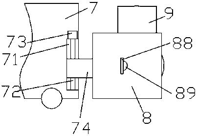
[0015] Such as figure 1 , figure 2 and image 3 As shown, an improved bridge deck laying device of the present invention includes a driving body 7 and a laying frame installed on the front end of the driving body 7, and the front end surface of the driving body 7 is provided with an up and down extension The lifting groove 71 is provided, and the lifting block 74 is connected with sliding fit in the lifting groove 71, and the main screw-shaped rod 72 extending up and down is connected in the internal spiral fit of the lifting block 74, and the front side end of the lifting block 74 is transparent. Out of the driving body 7 and fixedly connected with the rear end surface of the lower frame 8, the top extension tail of the main screw rod 72 is connected with the lifting groove 71 in rotation, and the bottom of the main screw rod 72 The extension tail is connected with the main driving machine 73, and the outer surface of the main driving machine 73 is installed in the inner b...
PUM
 Abstract
Description
Claims
Application Information
PatSnap Eureka turns technology decisions into work you can execute. Powered by our Innovation Knowledge Graph, it runs expert workflows across engineering, life sciences, materials and intellectual property. Get your review-ready output in minutes.


