Supercharge Your Innovation With Domain-Expert AI Agents!

Improved multipurpose bridge and road construction device

A road construction device and bridge technology, applied in soil protection, infrastructure engineering, construction, etc., can solve problems such as difficult quality assurance, low safety, and increased transportation costs, and achieve stable locking work, convenient operation, and simple structure Effect

Inactive Publication Date: 2018-06-29
赵林安
View PDF0 Cites 0 Cited by
  • Summary
  • Abstract
  • Description
  • Claims
  • Application Information

AI Technical Summary

Problems solved by technology

[0002] In the maintenance construction of bridges and roads, it is necessary to compact the pavement and subgrade. Due to the narrow working surface in the maintenance construction, the operation of large-scale compaction machinery is inconvenient, resulting in hidden quality problems caused by difficult compaction. Moreover, large-scale compaction machinery is inconvenient to transport , which increases the transportation cost. In addition, the existing small tamping machine can be used for tamping operations on the plane, but it is more difficult to tamp the earthwork on the inclined surface, so mechanical equipment cannot perform tamping operations on the inclined surface. In some cases, it is necessary to carry out manual compaction, using a manual mobile compaction machine, this compaction method is slow, the action area is small, and the energy consumption is relatively large, which also increases the maintenance construction cost, not only labor-intensive, low safety, but also The quality of construction is difficult to guarantee

Method used


Image

  • Improved multipurpose bridge and road construction device
  • Improved multipurpose bridge and road construction device
  • Improved multipurpose bridge and road construction device

Examples


Embodiment Construction

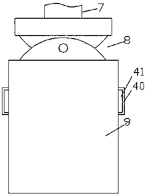
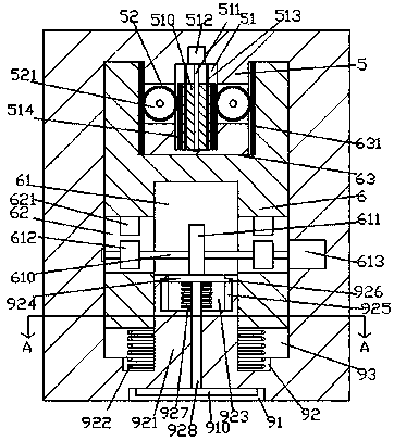
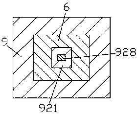
[0015] Such as Figure 1-Figure 4 As shown, an improved multi-purpose bridge and road construction device of the present invention includes a boom 7, a recliner 8 installed at the bottom of the boom 7 and a tamping body 9 installed at the bottom of the recliner 8 A sinking groove 91 is provided in the bottom end surface of the tamping body 9, a sliding cavity 93 is provided in the tamping body 9 on the upper side of the sinking trough 91, and a groove 92 is arranged in the inner bottom wall of the sliding cavity 93, The slide housing 93 is slidingly connected with the sliding frame body 6, the bottom end surface of the sliding frame body 6 is provided with a first sliding cavity 61, and the top end surface of the sliding frame body 6 is provided with a second sliding cavity 63, so The inner walls of the left and right sides of the first sliding cavity 61 are respectively provided with first through grooves 62, and the first sliding cavity 61 opposite to the first through groo...


PUM


Abstract

The invention discloses an improved multipurpose bridge and road construction device. The improved multipurpose bridge and road construction device comprises a lifting arm, an angle adjuster mounted at the bottom of the lifting arm and a rammer compactor body mounted at the bottom of the angle adjuster. A sunken groove is formed in the end face of the bottom of the rammer compactor body. A slidingcavity is formed in the portion, located on the upper side of the sunken groove, of the rammer compactor body. A groove is formed in the bottom wall of the interior of the sliding cavity. A sliding frame is connected to the interior of the sliding cavity in a sliding fit mode. A first sliding cavity is formed in the end face of the bottom of the sliding frame. A second sliding cavity is formed inthe end face of the top of the sliding frame. Through grooves are formed in the inner walls of the left and right sides of the first sliding cavity in a penetration mode. A pressing cam is connectedto the interior of the first sliding cavity in a transition fit mode and is opposite to the first through grooves on the left and right sides. A rotary shaft extending left and right is fixedly arranged on the pressing cam. The improved multipurpose bridge and road construction device is simple in structure, convenient to operate, capable of achieving stable locking operation of the pressing cam and improving the compaction safety, also capable of meeting the requirements for compaction at different angles and convenient to move and carry.

Description

technical field [0001] The invention relates to the technical field of tamping construction machinery, in particular to an improved multi-purpose bridge and road construction device. Background technique [0002] In the maintenance construction of bridges and roads, it is necessary to compact the pavement and subgrade. Due to the narrow working surface in the maintenance construction, the operation of large-scale compaction machinery is inconvenient, resulting in hidden quality problems caused by difficult compaction. Moreover, large-scale compaction machinery is inconvenient to transport , which increases the transportation cost. In addition, the existing small tamping machine can be used for tamping operations on the plane, but it is more difficult to tamp the earthwork on the inclined surface, so mechanical equipment cannot perform tamping operations on the inclined surface. In some cases, it is necessary to carry out manual compaction, using a manual mobile compaction ma...

Claims


Application Information

Patent Timeline
IPC IPC(8): E02D3/046
CPCE02D3/046
Inventor 赵林安
Owner 赵林安
Features
  • R&D
  • Intellectual Property
  • Life Sciences
  • Materials
  • Tech Scout
  • Unparalleled Data Quality
  • Higher Quality Content
  • 60% Fewer Hallucinations
Learn More