
Novel bearing isolation structure and installation method thereof

A technology of seismic isolation and support, which is applied in the direction of earthquake resistance, building components, building types, etc., can solve the problems of poor seismic isolation effect, difficult installation, and easy aging of components, so as to achieve good seismic isolation effect and avoid excessive pressure bearing , to avoid the effect of damage

Active Publication Date: 2018-06-29
NORTH CHINA UNIV OF WATER RESOURCES & ELECTRIC POWER
View PDF7 Cites 0 Cited by
  • Summary
  • Abstract
  • Description
  • Claims
  • Application Information

AI Technical Summary

Problems solved by technology

[0006] Aiming at technical problems such as poor seismic isolation effect, difficult installation and easy aging of components in the prior art, the present invention provides a new type of seismic isolation structure for bearings and its installation method

Method used


Image

  • Novel bearing isolation structure and installation method thereof
  • Novel bearing isolation structure and installation method thereof
  • Novel bearing isolation structure and installation method thereof

Examples


Embodiment 1

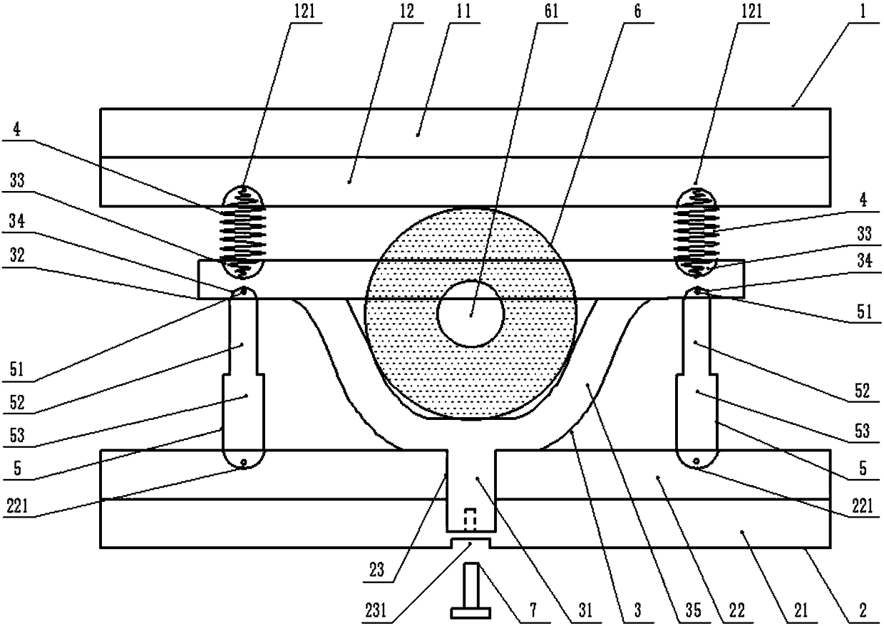
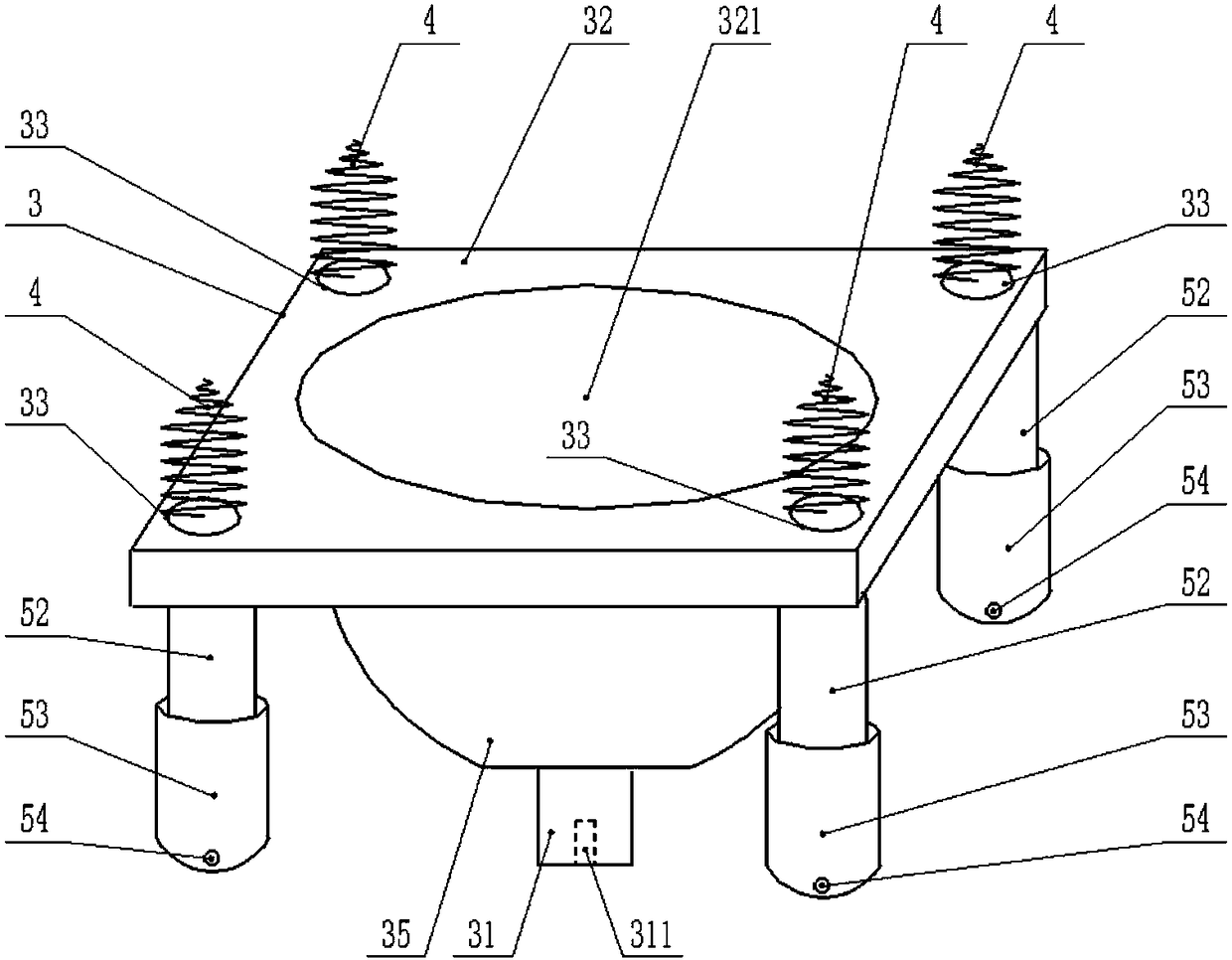
[0029] Such as Figure 1-2As shown, a new type of support isolation structure mainly includes a top plate 1, a bottom plate 2, a shock isolation member 3 and an elastic ball 6. The top plate 1 is divided into two layers, the upper layer is a fireproof layer-11, the lower layer is a steel plate-12, and the steel plate Spring fixing holes 121 are arranged at the four vertices of the lower surface of —12; the vibration isolation member 3 is arranged below the top plate 1, and the vibration isolation member 3 includes a fixed rod 31, an upper panel 32 and a groove 35, and the upper panel 32 is arranged on the vibration isolation unit. On the upper surface of the component 3, a circular hole 321 is provided at the center of the upper panel 32, the groove 35 is hemispherical and the mouth of the groove 35 is fixedly connected below the circular hole 321, and the four corners of the upper surface of the upper panel 32 are respectively provided with springs to fix Hole 2 33, spring fi...

Embodiment 2

[0031] Such as Figure 1-2 As shown, a new type of support isolation structure mainly includes a top plate 1, a bottom plate 2, a shock isolation member 3 and an elastic ball 6. The top plate 1 is divided into two layers, the upper layer is a fireproof layer-11, the lower layer is a steel plate-12, and the steel plate The lower surface of —12 is in a square matrix and is provided with spring fixing holes —121; the vibration isolation member 3 is arranged under the top plate 1, and the vibration isolation member 3 includes a fixed rod 31, an upper panel 32 and a groove 35, and the upper panel 32 is arranged on the vibration isolation unit. On the upper surface of the member 3, the upper panel 32 has a circular hole 321, the groove 35 is hemispherical and the mouth of the groove 35 is fixedly connected with the circular hole 321, and the four corners of the upper surface of the upper panel 32 are respectively provided with two spring fixing holes. 33. Spring fixing hole 2 33 cor...


PUM


Abstract

The invention discloses a novel bearing isolation structure and an installation method thereof, and belongs to the technical field of anti-seismic engineering of buildings. The novel bearing isolationstructure mainly comprises a top plate, a bottom plate, an isolation component and an elastic ball, wherein the isolation component is installed between the top plate and floor, and the isolation component comprises a fixed rod, an upper panel and a groove; the upper panel is installed on the upper surface of the isolation component, the upper panel is provided with a circular hole, and the groove is hemispherical and a groove opening is fixedly connected with the circular hole; second spring fixed holes are separately formed in four corners of the upper surface of the upper panel, and firsthinged supports are separately arranged in four corners of the lower surface of the upper panel; and the fixed rod is fixedly mounted under the groove, a first bolt hole is formed in the fixed rod, the elastic ball is arranged in the groove, a spherical cavity is arranged in the elastic ball, and active oil is injected into the spherical cavity. In summary, the novel bearing isolation structure has the advantages of reasonable structure, low construction cost, good seismic isolation effect and the like.

Description

technical field [0001] The invention belongs to the field of anti-seismic technology of building structures, and in particular relates to a novel support anti-seismic structure and an installation method thereof. Background technique [0002] The seismic isolation bearing refers to the supporting device set up by the structure to meet the seismic isolation requirements. It is to add a seismic isolation layer between the upper structure and the foundation, install a rubber seismic isolation bearing, and play a soft connection with the ground. Through such a technology , can offset about 80% of the energy of the earthquake. For example, laminated rubber bearings (or vibration-isolated rubber bearings, interlayer rubber pads, etc.). It is a structural member with low horizontal stiffness and high vertical stiffness, which can withstand large horizontal deformation and can be used as a part of the load-bearing system. Such anti-seismic technology comes from the research and de...

Claims


Application Information

Patent Timeline
Patent Type & Authority Applications(China)
IPC IPC(8): E04B1/36E04B1/98E04H9/02
Inventor 韩爱红梁娜郑惠军武宗良赵山王廷彦
Owner NORTH CHINA UNIV OF WATER RESOURCES & ELECTRIC POWER
Learn More