An Air Heat Collector with Vacuum Tubes Connectable in Series

An air heat collector and vacuum heat collecting tube technology, applied in the field of solar energy, can solve the problems that the heat collecting area and installation form cannot be flexibly applied, the warm air is mixed with cold air, and the cold and hot air are mixed, so as to avoid heat loss, The effect of improving the heating effect and reducing the cost of investment

Active Publication Date: 2020-02-21
浙江潮城科技发展有限公司
View PDF4 Cites 0 Cited by
  • Summary
  • Abstract
  • Description
  • Claims
  • Application Information

AI Technical Summary

Problems solved by technology

[0004] In the known technology, the known solar air heat collectors are limited by their heat collecting tubes, so they cannot be flexibly applied to different heat collecting areas and installation forms, and have poor applicability
In addition, in the existing solar air heat collectors, the heat collecting tubes are generally inserted directly into the air header, and the temperature difference between hot and cold air is used to automatically adjust, so that the wind output from the air header is warm air, but the hot and cold air in the air header is alternating. Mixed together, only relying on its automatic adjustment, the output warm air will often be mixed with cold air

Method used


Image

  • An Air Heat Collector with Vacuum Tubes Connectable in Series
  • An Air Heat Collector with Vacuum Tubes Connectable in Series
  • An Air Heat Collector with Vacuum Tubes Connectable in Series

Examples


Embodiment Construction

[0025] The following are specific embodiments of the present invention and in conjunction with the accompanying drawings, the technical solutions of the present invention are further described, but the present invention is not limited to these embodiments.

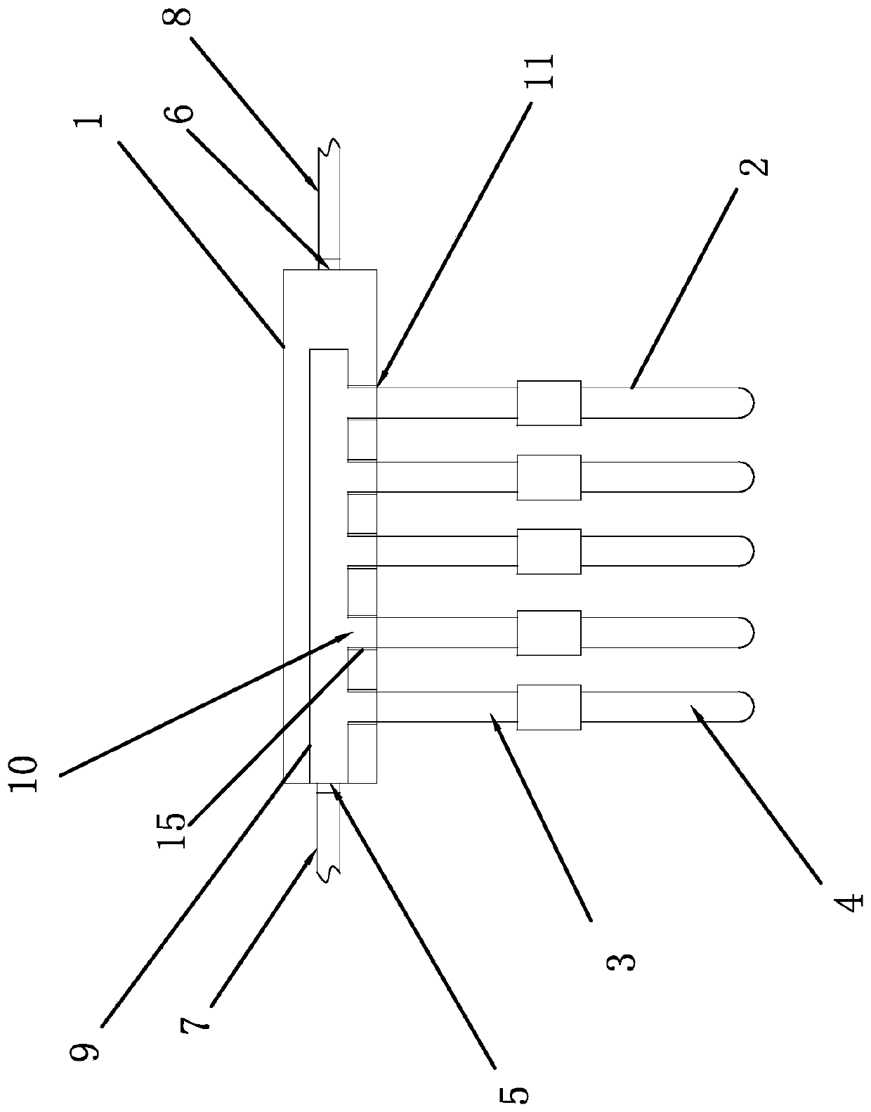
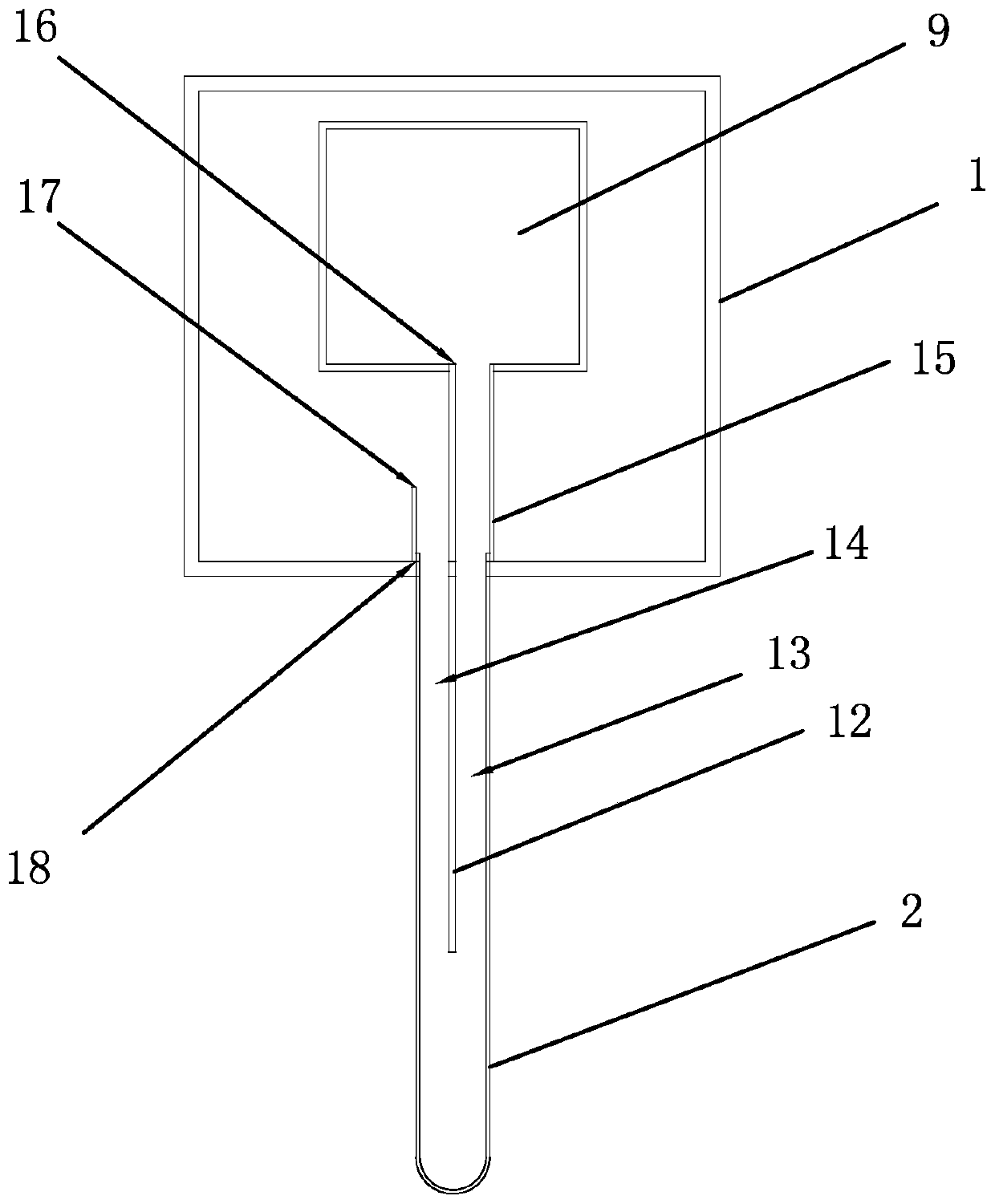
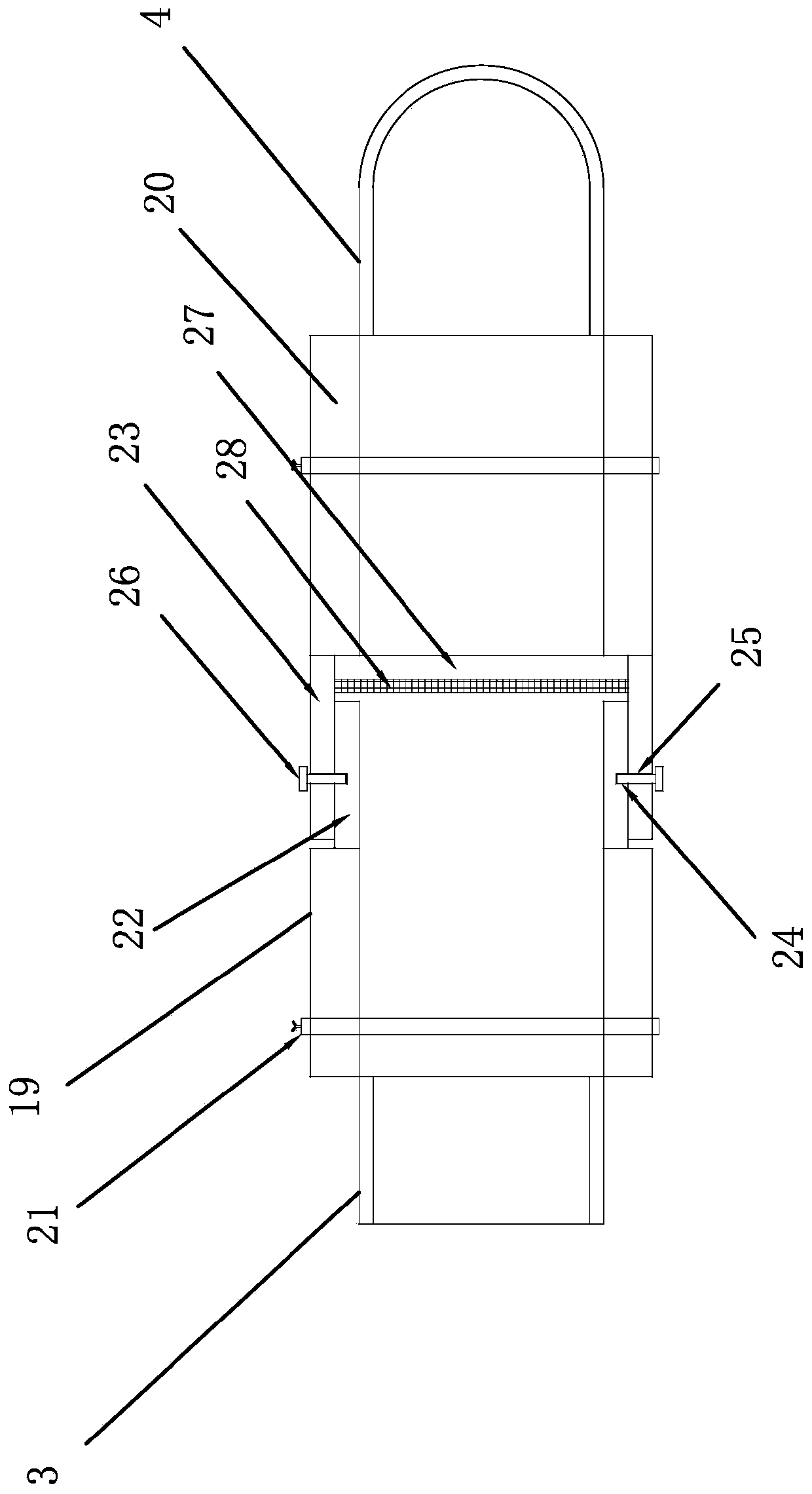
[0026] Such as figure 1 , figure 2 , image 3 , Figure 4 As shown, the air heat collector of the vacuum tube type, which can be spliced ​​in series, includes an air header 1 and a vacuum heat collection tube 2. The two ends of the air header 1 are respectively provided with an air inlet 5 and a warm air outlet 6, and the air inlet 5 is connected to There is a cold air pipe 7, the warm air outlet 6 is connected to a warm air pipe 8, and the air header 1 is provided with a dispersion pipe 9, one end of the dispersion pipe 9 is a closed structure, and the other end is connected to the cold air pipe 7 inserted into the air header 1, and the air header 1 is dispersed. The lower end of the pipe 9 is provided with a number o...


PUM


Abstract

The invention provides an air heat collector capable of being spliced to vacuum tubes in series connection, and belongs to the technical field of solar energy. The air heat collector comprises an airheader and vacuum heat collection tubes. An air dispersion tub is arranged in the air header. A plurality of equidistantly-arrayed air feed inlets are arranged at the lower end of the air dispersion tube. A plurality of equidistantly-arrayed connectors are arranged at the lower end of the air header. One end of each vacuum heat collection tube is closed, and the other ends of the vacuum heat collection tubes are open. The open ends of the vacuum heat collection tubes are inserted into the connectors at the lower end of the air header. Flow-dividing stop plates are arranged in portions, close to the open ends, of the vacuum heat collection tubes. Flow-dividing cylinders sleeve the ends, inserted into the collectors, of the vacuum heat collection tubes. Each vacuum heat collection tube comprises at least one splicing tube and a main tube. The splicing tubes are collected with the main tubes through splicing components hermetically. The splicing tubes are connected with one another through splicing components hermetically. The air heat collector has the advantages that output hot air can be prevented from being mixed with cold air, the lengths of the vacuum heat collection tubes are controlled through splicing of the splicing tubes and the main tubes, and the application range is wide.

Description

technical field [0001] The invention belongs to the technical field of solar energy and relates to an air heat collector of vacuum tube type which can be spliced ​​in series. Background technique [0002] With the increasing shortage of coal, oil and other energy sources and the increasing pressure on environmental protection, countries have begun to promote renewable energy. Among them, the development and utilization of solar energy has become the hottest new favorite among renewable energy sources, and the development and utilization of solar energy has become an irresistible trend. . [0003] At present, among the many forms of solar energy utilization, the most mature, most economical, and most closely related to buildings is solar thermal utilization. Solar air collectors are one of the main forms of solar thermal utilization. The development of solar air collectors in my country has also begun to be widely used. In addition to residential heating and air conditionin...

Claims


Application Information

Patent Timeline
Patent Type & Authority Patents(China)
IPC IPC(8): F24S10/40F24S10/70F24S80/00
CPCY02E10/44
Inventor 王国伟朱文豪黄飞李君
Owner 浙江潮城科技发展有限公司
Why Eureka
Try Eureka