

Angular transducer and angular transducer system
An angle sensor and angle technology, which is applied in the direction of transmitting sensing components using electric/magnetic devices, can solve problems such as large constraints in structure or setting, and achieve the effect of reducing angle errors
- Summary
- Abstract
- Description
- Claims
- Application Information
AI Technical Summary
Problems solved by technology
Method used
Image

Examples
no. 1 Embodiment approach
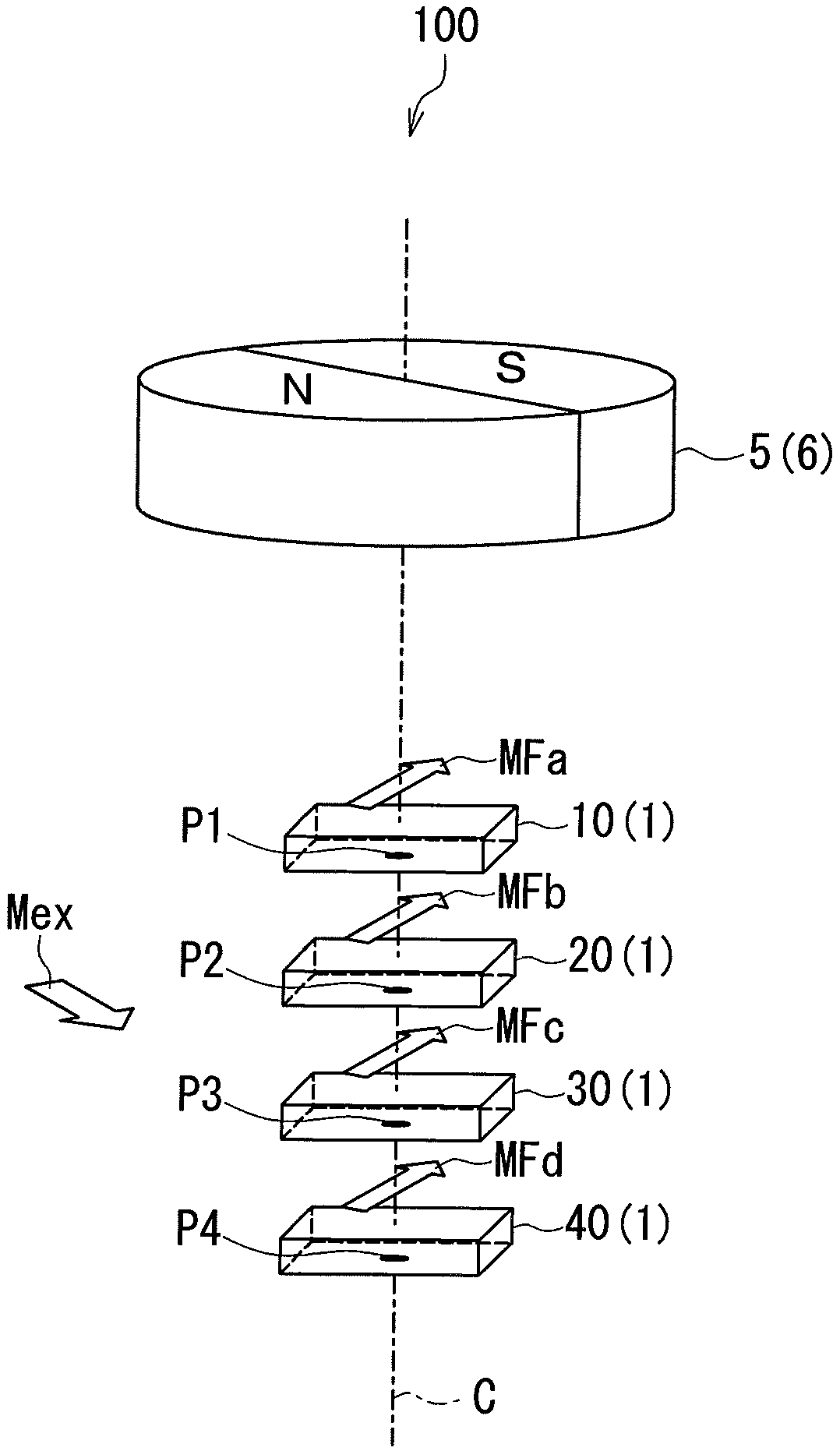
[0044] Hereinafter, embodiments of the present invention will be described in detail with reference to the drawings. First, refer to figure 1 , the schematic configuration of the angle sensor system according to the first embodiment of the present invention will be described. The angle sensor system 100 according to the present embodiment includes the angle sensor 1 and the magnetic field generating unit 5 according to the present embodiment. Angle sensor 1 is in particular a magnetic angle sensor. The magnetic field generator 5 generates a magnetic field to be detected by the angle sensor 1 . Hereinafter, the magnetic field to be detected by the angle sensor 1 is referred to as the target magnetic field.
[0045] The magnetic field generator 5 in this embodiment is a columnar magnet 6 . The magnet 6 has N poles and S poles arranged symmetrically about an imaginary plane including the central axis of the cylinder as a center. The magnet 6 rotates around the center axis of...
no. 2 Embodiment approach
[0156] Next, a second embodiment of the present invention will be described. First, refer to Figure 9 , the configuration of the angle sensor system 100 according to this embodiment will be described. The angle sensor system 100 according to this embodiment differs from the first embodiment in the following points. Such as Figure 9 As shown, in the present embodiment, the first to fourth detection positions P1 to P4 are located on the same plane parallel to one end face of the magnet 6 . Hereinafter, a virtual plane including the first to fourth detection positions P1 to P4 is referred to as a reference plane P. As shown in FIG. In this embodiment, in particular, the first to fourth detection positions P1 to P4 are defined so that the distances from the magnetic field generating unit 5 are equal to each other. 1st to 4th detection positions P1 to P4 such as Figure 9 The illustration is on the reference plane P, but it may be on the circumference of a circle with the ro...
no. 3 Embodiment approach
[0171] Next, a third embodiment of the present invention will be described. First, refer to Figure 11 , the configuration of the angle sensor 1 according to the present embodiment will be described. The configuration of the angle sensor 1 according to this embodiment differs from the first and second embodiments in the following points. In this embodiment, the first to fourth vector generation units 15, 25, 35, and 45 in the first and second embodiments are not provided. The angle sensor 1 according to the present embodiment includes an angle calculation unit 250 instead of the angle calculation unit 50 in the first and second embodiments. The angle computing unit 250 can be realized by, for example, an ASIC or a microcomputer.
[0172] In this embodiment, as in the first and second embodiments, the vector Y1 represents the first composite magnetic field information, the vector Y2 represents the second composite magnetic field information, and the vector Y3 represents the ...
PUM
 Abstract
Description
Claims
Application Information