

Installation method of optical fiber aerodynamic force measuring balance and optical fiber strain gauge
An aerodynamic and strain gauge technology, applied in measuring devices, fluid pressure measurement using optical methods, aerodynamic tests, etc. and other problems, to solve the difficulties of laying, improve static performance, and ensure the effect of installation quality
Active Publication Date: 2018-06-29
中国空气动力研究与发展中心超高速空气动力研究所
View PDF8 Cites 7 Cited by
- Summary
- Abstract
- Description
- Claims
- Application Information
AI Technical Summary
Problems solved by technology
Due to the very small size of the optical fiber strain gauge, the installation surface is arc-shaped, and its lead-out wire is a bare optical fiber, its flexibility and bending resistance are poor, and the no-loss bending radius is not less than 5mm, making its installation and lead-out It is difficult to lay the wires, and it is easy to install loosely or in an incorrect installation position during the installation process, which seriously affects the performance of the fiber optic balance.
Method used
View moreImage
Smart ImageViewing Examples

Examples
Embodiment 1
[0050] A method for installing an optical fiber strain gauge in an above-mentioned optical fiber pneumatic measuring balance, comprising the following steps:
Login to View More PUM
 Abstract
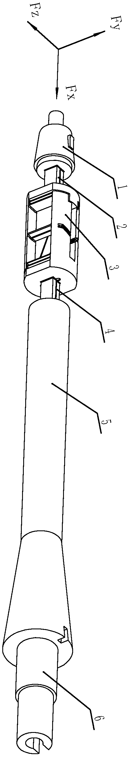
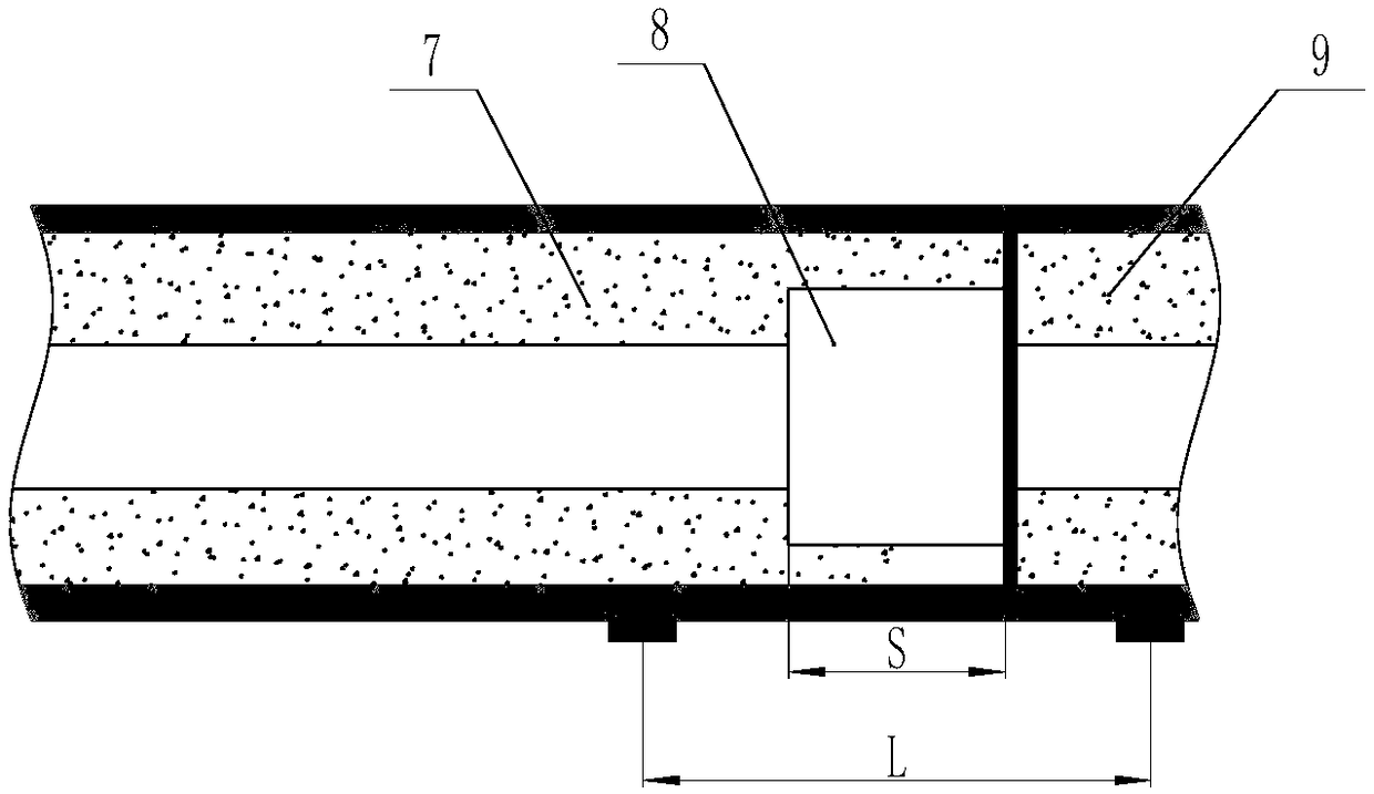
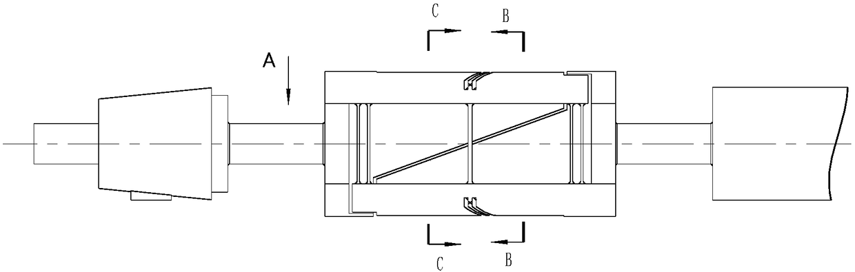
The invention discloses an installation method of an optical fiber aerodynamic force measuring balance and an optical fiber strain gauge for high-ultrasonic speed and low-density air tunnels. The installation method has the advantages that by designing a circular arc channel for positioning installing an optical fiber F-P strain gauge on a measuring beam of the optical fiber aerodynamic force measuring balance, the problems of low installation strength, and easiness in offset of the installation position due to small size of the optical fiber F-P strain gauge can be effectively solved, and theinstallation quality of the optical fiber F-P strain gauge is guaranteed; by designing holes and grooves for leading out optical fibers for each optical fiber strain gauge on a structure body of theoptical fiber aerodynamic force measuring balance, the problem of difficulty in layout of led-out wires in the optical fiber strain gauge can be effectively solved; by establishing an adhering installation technology of the optical fiber F-P strain gauge, the installation quality of the optical fiber strain gauge is guaranteed, the static property of the optical fiber balance is improved, and therequirement of aerodynamic measuring accuracy of the high-ultrasonic speed and low-density air tunnel of an advanced aerospace craft model is met.
Description
technical field [0001] The invention belongs to the technical field of aerospace force measurement test, in particular to a wind tunnel test model aerodynamic force measurement balance, in particular to an optical fiber aerodynamic force measurement balance and an optical fiber strain gauge installation process applied to a hypersonic low-density wind tunnel. Background technique [0002] The hypersonic low-density wind tunnel is a tool for studying rarefied gas dynamics, and it is also a ground test device for simulating high-altitude and high-speed flight conditions of spacecraft. In this wind tunnel, tests of the aerodynamic characteristics of spacecraft models such as missiles, decoys, satellites and spacecraft return capsules can be carried out. [0003] With the development of my country's aerospace technology, higher and higher requirements are put forward for the precise measurement of aerodynamic forces of various spacecraft models. When carrying out model aerodyna...
Claims
Login to View More Application Information
Patent Timeline
 Patent Type & AuthorityApplications(China)
IPC IPC(8): G01M9/06G01L11/02
CPCG01L11/02G01M9/062Y02T90/00
Inventor闵夫冉曾令戴金雯杨彦广邱华诚钟少龙李绪国冯双
Owner中国空气动力研究与发展中心超高速空气动力研究所