A Boundary Condition Simulation Device for Acoustic Closed-End Inlet of Liquid Flow System

A boundary condition, simulation device technology, applied in measurement devices, fluid dynamics tests, testing of machine/structural components, etc., can solve problems such as cavitation, large flow resistance, etc., to achieve lightening of the burden, high flow velocity, and uniform flow field Effect

Active Publication Date: 2019-10-01
XIAN AEROSPACE PROPULSION INST
View PDF5 Cites 0 Cited by
  • Summary
  • Abstract
  • Description
  • Claims
  • Application Information

AI Technical Summary

Problems solved by technology

[0003] The purpose of the present invention is to overcome the above-mentioned deficiencies in the prior art, provide a liquid flow system acoustic closed-end inlet boundary condition simulation device, and solve the problem of excessive flow resistance and serious cavitation of the traditional structure for simulating the acoustic closed-end

Method used


Image

  • A Boundary Condition Simulation Device for Acoustic Closed-End Inlet of Liquid Flow System
  • A Boundary Condition Simulation Device for Acoustic Closed-End Inlet of Liquid Flow System

Examples


Embodiment Construction

[0019] Below in conjunction with accompanying drawing and specific embodiment the present invention is described in further detail:

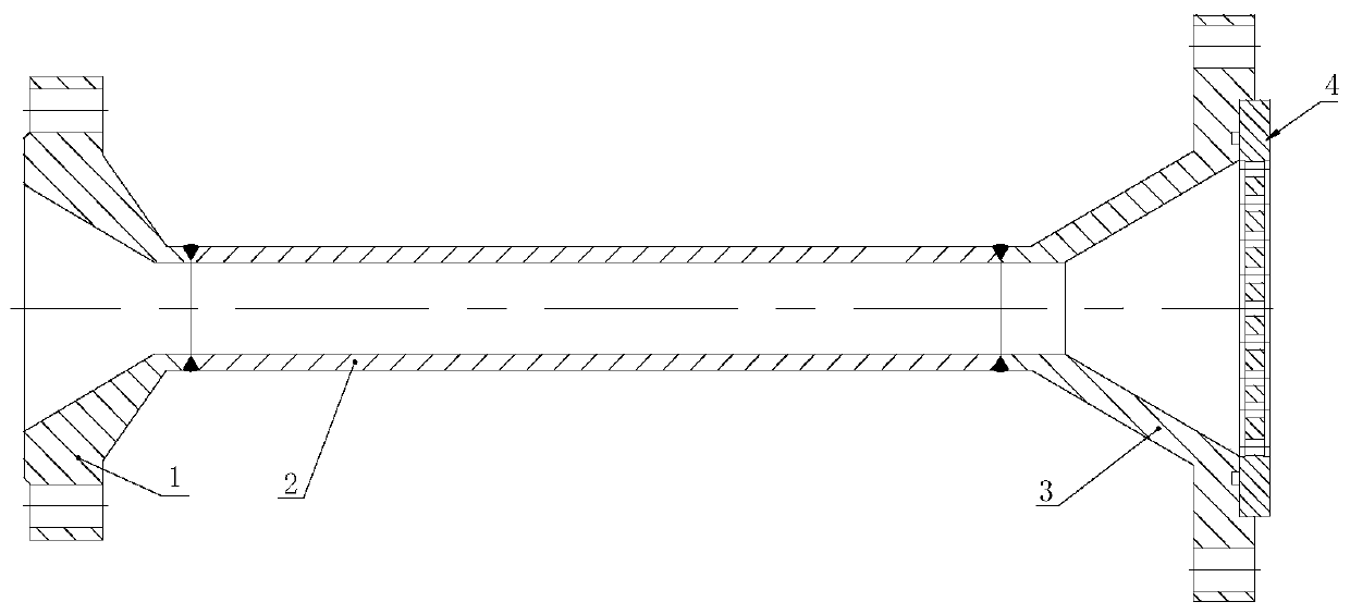
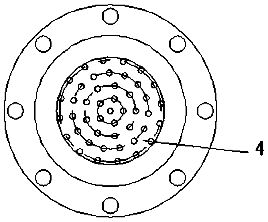
[0020] Such as figure 1 Shown is a schematic cross-sectional view of the center of the simulation device. It can be seen from the figure that a liquid flow system acoustic closed-end inlet boundary condition simulation device is characterized in that it includes a contraction cone 1, a throttle tube 2, an expansion cone 3 and a porous rectification grid 4 ; Wherein, the throttling tube 2 is a hollow cylindrical structure; the contraction cone 1 and the expansion cone 3 are both hollow conical structures; the contraction cone 1 is fixedly installed on the axial end of the throttle tube 2 along the axial direction; and the contraction cone 1 The axial small-diameter end is fixedly connected to the throttle tube 2; the expansion cone 3 is fixedly installed on the other axial end of the throttle tube 2; and the axial small-diameter end of the expans...


PUM


Abstract

The invention discloses a simulating device for acoustic closed end inlet boundary conditions of a fluid flow system and relates to the field of simulating devices for acoustic closed end inlet boundary conditions. The simulating device comprises a recession cone, a throttle pipe, a diverging cone and a porous diffuser grid, wherein the throttle pipe is of a hollow cylindrical structure; the recession cone and the diverging cone are both in hollow conical structures; the recession cone is fixedly arranged at one axial end of the throttle pipe along the axial direction; in addition, the axialminor-diameter end of the recession cone is fixedly connected with the throttle pipe; the diverging cone is fixedly arranged at the other axial end of the throttle pipe along the axial direction; theaxial minor-diameter end of the diverging cone is fixedly connected with the throttle pipe; the porous diffuser grid is horizontally and fixedly arranged on the major-diameter end face of the diverging cone; besides, the porous diverging cone covers a through hole opening of the diverging cone; the major-diameter end of the recession cone is an inlet section; and the major-diameter end of the diverging cone is an outlet end. According to the simulating device disclosed by the invention, the problems that a traditional structure for simulating the acoustic closed end has over-great flow resistance and is seriously corroded are solved.

Description

technical field [0001] The invention relates to the field of an acoustic closed-end inlet boundary condition simulation device, in particular to a liquid flow system acoustic closed-end inlet boundary condition simulation device. Background technique [0002] In the pump-pressed liquid rocket engine, the centrifugal pump is used as the inlet boundary of the delivery system after the pump. Due to the high-speed rotation of the centrifugal pump blades, the internal flow velocity of the blades is very high and the inertia of the fluid is large, making the centrifugal pump close to the acoustic closed end of constant flow. Boundary conditions. When simulating the outlet boundary strip of a centrifugal pump on a liquid flow test bench, according to the traditional method of simulating boundary conditions, only a throttle ring with a large pressure drop is set, and a throttle orifice with a large flow resistance needs to be designed at the inlet of the liquid flow test bench , th...

Claims


Application Information

Patent Timeline
Patent Type & Authority Patents(China)
IPC IPC(8): G01M10/00
Inventor 刘上张兴军程晓辉陈炜卢永乐吕鹏翾邢理想赵瑞国
Owner XIAN AEROSPACE PROPULSION INST
Why Eureka
Try Eureka