

High-stability and high-precision current source circuit
A high-precision, current source technology, applied in the direction of adjusting electrical variables, control/regulating systems, instruments, etc., can solve the problems of poor current accuracy, unstable output current range, long response time, etc., to improve control accuracy and efficiency. , the effect of high-precision current source output
- Summary
- Abstract
- Description
- Claims
- Application Information
AI Technical Summary
Problems solved by technology
Method used
Image

Examples
Embodiment Construction
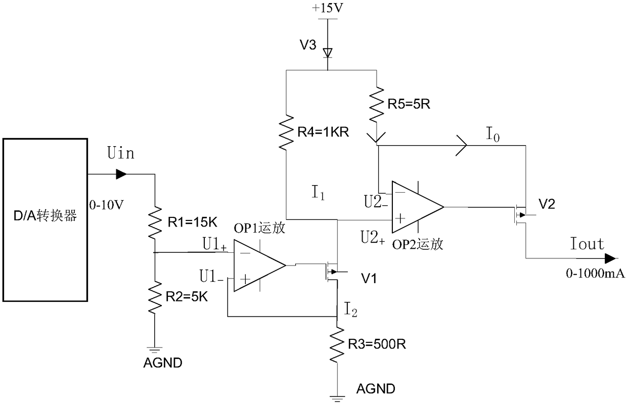
[0013] The output terminal of the D / A converter is connected in series with resistors R1 and R2 to AGND. When the D / A converter outputs the voltage Uin, a voltage U1+=Uin*(R2 / (R1+R2)) will be generated at the connection point between R1 and R2.
[0014] The negative terminal of the first operational amplifier OP1 is connected to the connection point of the resistors R1 and R2. The positive terminal of the first operational amplifier OP1 is divided into two circuits, one is connected to AGND through the resistor R3, and the other is connected to the drain of the first field effect transistor V1 to form a positive feedback connection to generate a voltage U1-. The output end of the first operational amplifier OP1 is connected to the gate of the first field effect transistor V1. The negative feedback circuit jointly formed by OP1 and V1 makes U1+=U1-, and then I2=U1- / R3=U1+ / R3. Because the first operational amplifier OP1 is positive feedback connection, the settling time of U1-...
PUM
 Abstract
Description
Claims
Application Information