
Tripping mechanism and surge protection device equipped with tripping mechanism

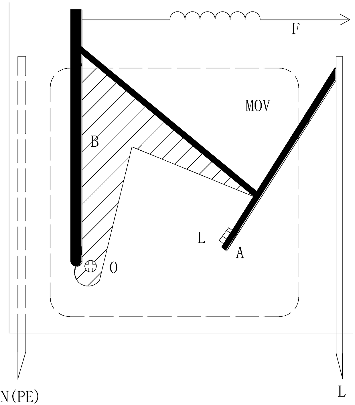
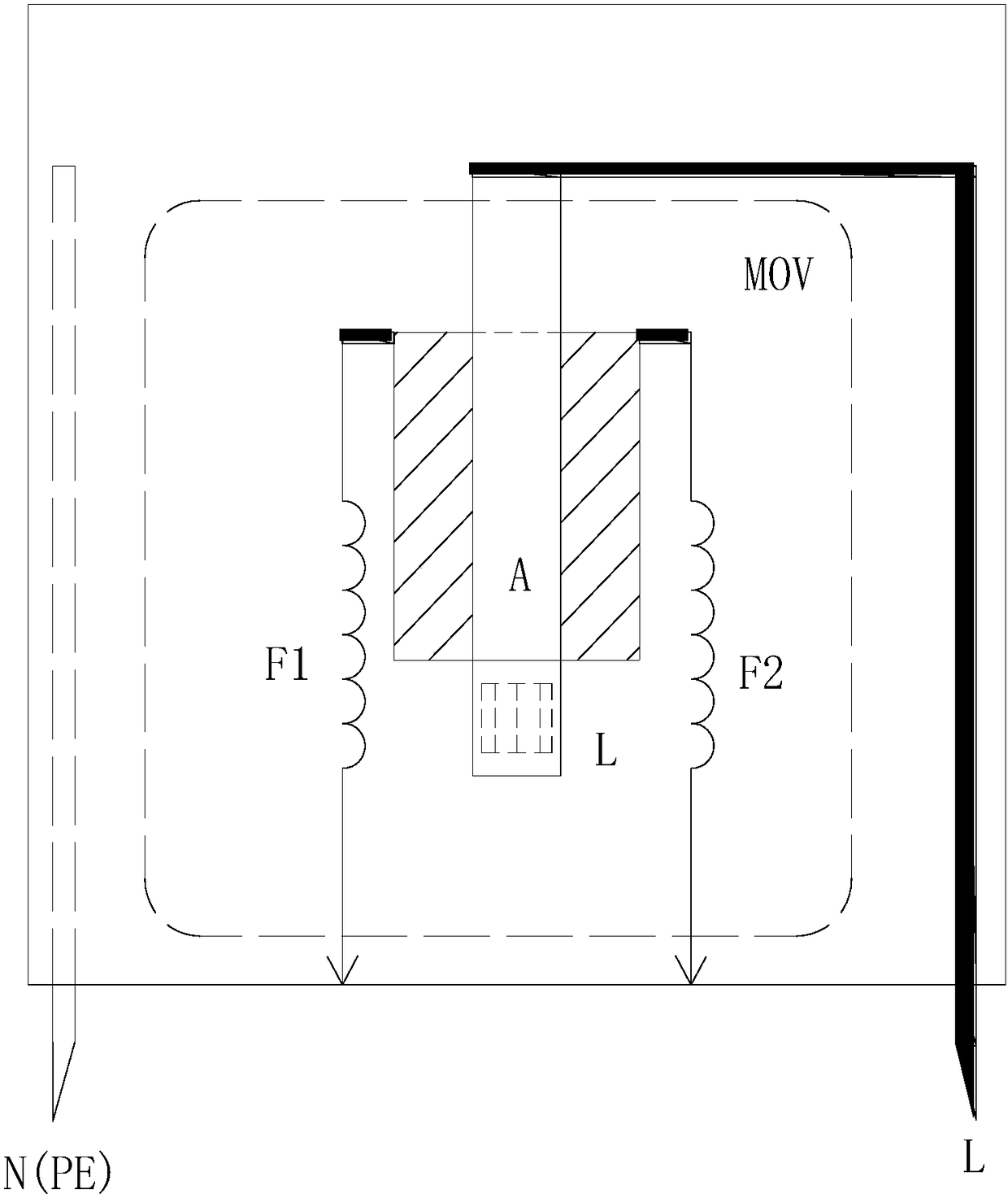
A technology of surge protector and tripping mechanism, applied in emergency protection circuit devices for limiting overcurrent/overvoltage, emergency protection circuit devices, protection switch operation/release mechanisms, etc. Blocker deviation, breakdown, etc.

Pending Publication Date: 2018-06-29
广东立信防雷科技有限公司
View PDF0 Cites 4 Cited by
  • Summary
  • Abstract
  • Description
  • Claims
  • Application Information

AI Technical Summary

Problems solved by technology

[0005] but either figure 1 The push-off mechanism is still figure 2 There are examples of tripping failures in the actual use and experiments of the cut-off mechanism
The reason is figure 1 The release mechanism has insufficient separation range and occasional wire drawing of welding materials, so that the distance between the electrode of the surge protector and the electrode welding point of the varistor is not enough, resulting in arc discharge
figure 2 In order to make the mechanism run stably, the breaking mechanism of the varistor adopts a large-area cutting piece, but when the piezoresistor heats up, there is a phenomenon that the breaking piece deviates, and at the same time, due to the thickness limit of the spacer in the process, there is a breakdown phenomenon

Method used


Image

  • Tripping mechanism and surge protection device equipped with tripping mechanism
  • Tripping mechanism and surge protection device equipped with tripping mechanism
  • Tripping mechanism and surge protection device equipped with tripping mechanism

Examples


Embodiment Construction

[0024] In order to facilitate the understanding of the present invention, the present invention will be described more fully below with reference to the relevant drawings.

[0025] It should be noted that when an element is considered to be "connected" to another element, it may be directly connected to and integrally integrated with the other element, or there may be an intervening element at the same time. The terms "mounted", "one end", "the other end" and similar expressions are used herein for the purpose of description only.

[0026] Unless otherwise defined, all technical and scientific terms used herein have the same meaning as commonly understood by one of ordinary skill in the art of this technology. The terminology used in the description herein is only for the purpose of describing specific embodiments, and is not intended to limit the present invention. As used herein, the term "and / or" includes any and all combinations of one or more of the associated listed ite...


PUM


Abstract

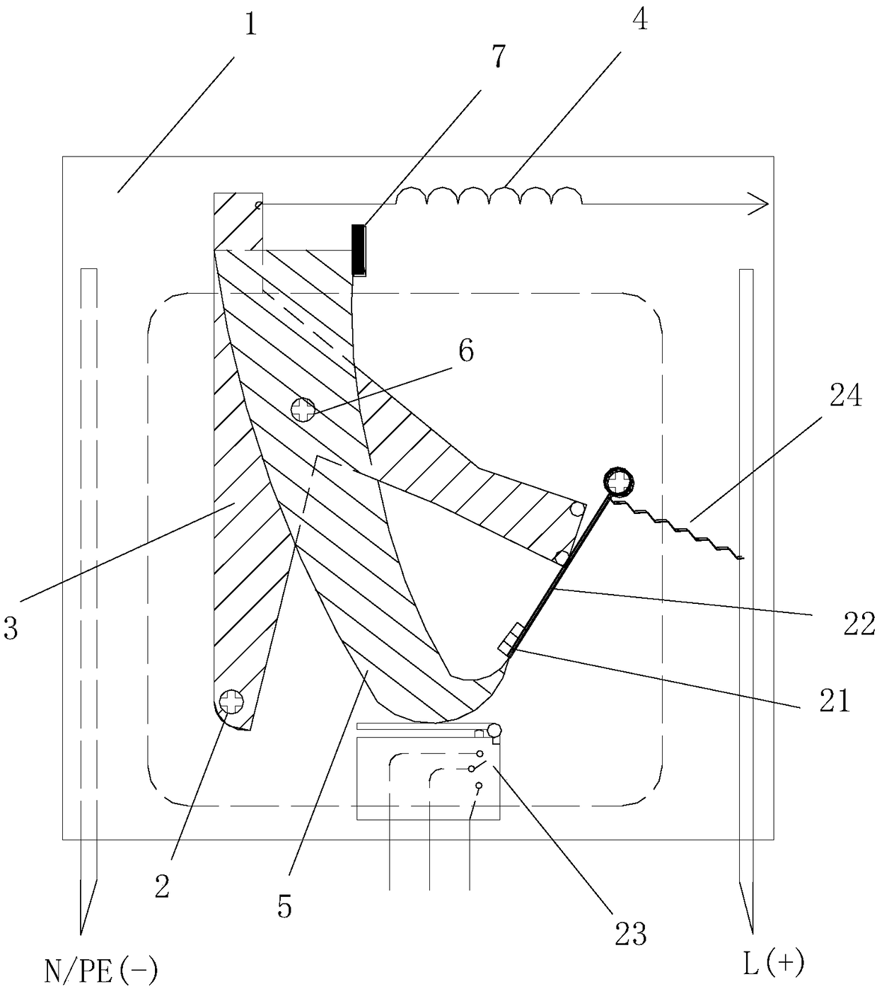
The invention discloses a tripping mechanism and a surge protection device equipped with the tripping mechanism. The tripping mechanism comprises a base, a push-off piece, a traction component, an interception piece and a blockage point, wherein an electrode connecting component of a to-be-tripped protective device is welded to an electrode connecting point of the to-be-tripped protective device through soldering tin; one end of the push-off piece is rotatably mounted on the base, and the other end of the push-off piece presses the electrode connecting component downwards through the tractionof the traction component; and the interception piece is rotatably mounted on the push-off piece, and the blockage point is fixed on the base. When the soldering tin on an electrode point is molten, the push-off piece which presses the electrode downward continuously presses and moves downwards under the continuous traction of the traction component so as to pull the interception piece to move therewith; and the interception piece is blocked by virtue of the blockage point and then rotates, one end of the interception piece can utilize the blockage force of the blockage point, and thus the relative other end of the interception piece is rotated towards the electrode to the space between the electrode point and the electrode.

Description

technical field [0001] The invention relates to the field of lightning protection equipment, in particular to a tripping mechanism and a surge protector equipped with the tripping mechanism. Background technique [0002] The tripping mechanism and tripping monitoring or indication of the surge protector are the necessary mechanisms for the safe operation of the surge protector. The current tripping mechanism mostly adopts the thermal tripping method, which mainly includes push-off type and cut-off type. Its representative organizations are as follows: figure 1 and figure 2 shown. The principle is that when the surge protector fails to generate heat, the low-temperature welding at the electrode connection point in the figure melts, and the contact electrodes are separated, thereby achieving the purpose of tripping. [0003] figure 1 The push-off mechanism is mainly composed of surge protector (ie surge protector) connecting electrode A, push-off piece B and spring F. Whe...

Claims


Application Information

Patent Timeline
IPC IPC(8): H01H71/20H01H73/18H02H9/00H02H9/04
CPCH02H9/005H02H9/042H01H71/20H01H73/18
Inventor 何朝文何丹何锡华丁竞欣
Owner 广东立信防雷科技有限公司
Learn More