Plasma pyrolysis system

A plasma and pyrolysis technology, which is applied in the fields of plasma, production of combustible gas, gasification process, etc., can solve the problems of not meeting the application requirements of chemical raw materials, affecting the quality of synthesis gas, consuming the heat of gasifier, etc. Cost, improve efficiency, save power

Active Publication Date: 2016-05-11
JINING XINRUIDA INFORMATION TECH CO LTD
View PDF6 Cites 3 Cited by
  • Summary
  • Abstract
  • Description
  • Claims
  • Application Information

AI Technical Summary

Problems solved by technology

[0002] The gasification agent used in the conventional gasification device is water vapor + air or water vapor + oxygen. When the gasifier is working, the water vapor + air or water vapor + oxygen are directly sent into the gasifier to make the water vapor and Coal undergoes a gas-forming reaction to generate synthesis gas, which is an endothermic reaction that requires the oxidation reaction of air or oxygen and carbon to provide heat for it. The gasification rate of this gasification method is low, and at the same time, a large amount of Carbon dioxide waste gas not only affects the quality of synthesis gas, but also causes a large amount of greenhouse gas emissions in post-production
Due to the low calorific value of domestic waste and the low content of fixed carbon in its chemical composition, if conventional gasification technology is used to gasify domestic waste, the endothermic reaction between water vapor and domestic waste will consume the energy of the gasifier. The gasification furnace needs to add coal fuel and input air or oxygen to support the combustion, so that the exhaust gas content in the synthesis gas is high, and the useful components in the obtained synthesis gas are quite low, almost exhaust gas, which cannot meet the application requirements of chemical raw materials

Method used


Image

  • Plasma pyrolysis system
  • Plasma pyrolysis system
  • Plasma pyrolysis system

Examples


Embodiment 1

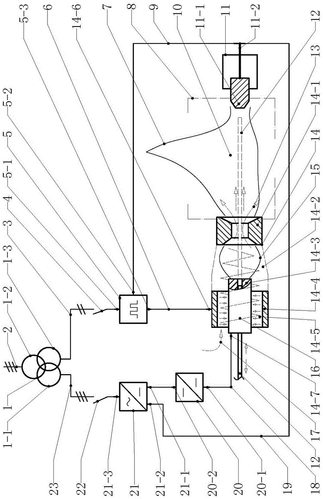
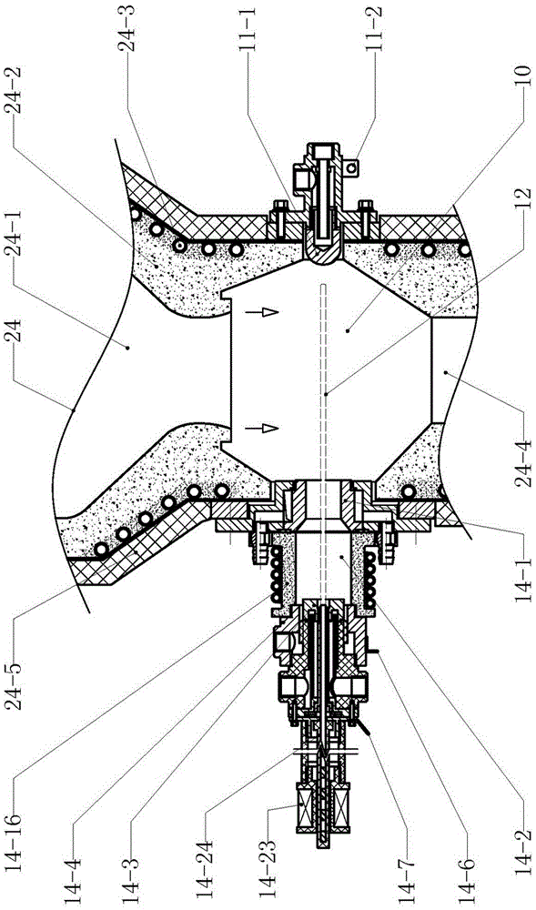
[0019] Example 1 figure 1 and figure 2 In the illustrated embodiment, the plasma system is composed of an isolation transformer 1, a three-phase rectifier 22, a high-frequency power supply 5, a first isolator 20, a second isolator 21 and a plasma device, and the isolation transformer 1 has a three-phase input winding 1-2. The three-phase output winding 1-1 and the single-phase output winding 1-3, the three-phase input winding 1-2 of the isolation transformer 1 is connected to the three-phase power frequency power supply line, and the three-phase rectifier 21 has a three-phase AC input interface 21-3 connection, DC output interface 21-1 connection and DC loop interface 21-2 connection, the three-phase output winding 1-1 of the isolation transformer 1 is connected to the three-phase winding 1-1 through the three-phase transmission line 23 and the three-pole switch 22 The three-phase AC input interface 21-3 of the rectifier 21; the high-frequency power supply 5 has a power fr...


PUM


Abstract

A plasma pyrolysis system relates to a plasma device and comprises a triphase rectifier, a high frequency power source and a plasma device; a triphase alternating current circuit is connected to a triphase alternating current input interface of the triphase rectifier; a monophase alternating current circuit is connected to a working frequency input interface of a high frequency power source; an isolator is arranged in the system; a direct current output interface of the triphase rectifier is connected to a direct current input end of the isolator; the plasma device consists of a first discharging component and a second discharging component; a first electrode, a second electrode, a third electrode are arranged in the first discharging component; a fourth electrode is arranged in the second discharging component; a high frequency output interface of the high frequency power source is connected to the first electrode; the direct current output end of the isolator is connected to the second electrode; a direct current loop interface of the triphase rectifier is connected to the fourth electrode. A plasma gasifying manner is adopted to perform ionization activation and then perform pyrolysis treatment through a second-class hyperthermia plasma arc on water vapor to dissolve the water vapor into active substances of hydrogen and oxygen to be used as a gasifying agent.

Description

technical field [0001] The invention relates to electromechanical equipment, in particular to a power supply for plasma equipment. Background technique [0002] The gasification agent used in the conventional gasification device is water vapor + air or water vapor + oxygen. When the gasifier is working, the water vapor + air or water vapor + oxygen are directly sent into the gasifier to make the water vapor and Coal undergoes a gas-forming reaction to generate synthesis gas, which is an endothermic reaction that requires the oxidation reaction of air or oxygen and carbon to provide heat for it. The gasification rate of this gasification method is low, and at the same time, a large amount of Carbon dioxide waste gas not only affects the quality of synthesis gas, but also causes a large amount of greenhouse gas emissions in post-production. Due to the low calorific value of domestic waste and the low content of fixed carbon in its chemical composition, if conventional gasific...

Claims


Application Information

Patent Timeline
Patent Type & Authority Applications(China)
IPC IPC(8): C10J3/00H05H1/34
CPCC10J3/00C10J2200/12C10J2300/092C10J2300/0946C10J2300/0976C10J2300/1238H05H1/34
Inventor 周开根
Owner JINING XINRUIDA INFORMATION TECH CO LTD
Why Eureka
Try Eureka