
European style lay-in ceiling and mounting method

A European-style downgrade and suspended ceiling technology, applied in the field of building decoration, can solve the problems of reducing the stability of the three-stage suspended ceiling, reducing the cleanliness of the construction environment, and the inability to guarantee the construction quality, and achieves novel structural design, shortened construction period, and structural simple effect

Pending Publication Date: 2018-07-03
ZHEJIANG YASHA DECORATION
View PDF14 Cites 10 Cited by
  • Summary
  • Abstract
  • Description
  • Claims
  • Application Information

AI Technical Summary

Problems solved by technology

In the process of realizing the invention, the inventor found that the above-mentioned three-level suspended ceiling has the following disadvantages: first, the weight of the three-level suspended ceiling is relatively large, and the damage to the original concrete on the top surface caused by hanging the three-level suspended ceiling with a hanging rod is relatively large ; The stability of the three-level suspended ceiling is reduced, and the construction quality cannot be guaranteed; second, the top surface needs to be drilled according to the position of the attachment rod at the construction site, which reduces the cleanliness of the construction environment and prolongs the construction period; Third, the length of the hanging rod needs to be processed on site according to the height of the central unit, which is time-consuming and laborious

Method used


Image

  • European style lay-in ceiling and mounting method
  • European style lay-in ceiling and mounting method
  • European style lay-in ceiling and mounting method

Examples


Embodiment Construction

[0024] The directional terms such as up, down, left, right, front, back, front, back, top, and bottom that are mentioned or may be mentioned in this specification are defined relative to the structures shown in the drawings. The words " "Inside" and "outside" respectively refer to the direction toward or away from the geometric center of a specific component. They are relative concepts, so they may change accordingly according to their different positions and different usage states. Accordingly, these or other directional terms should not be construed as limiting terms.

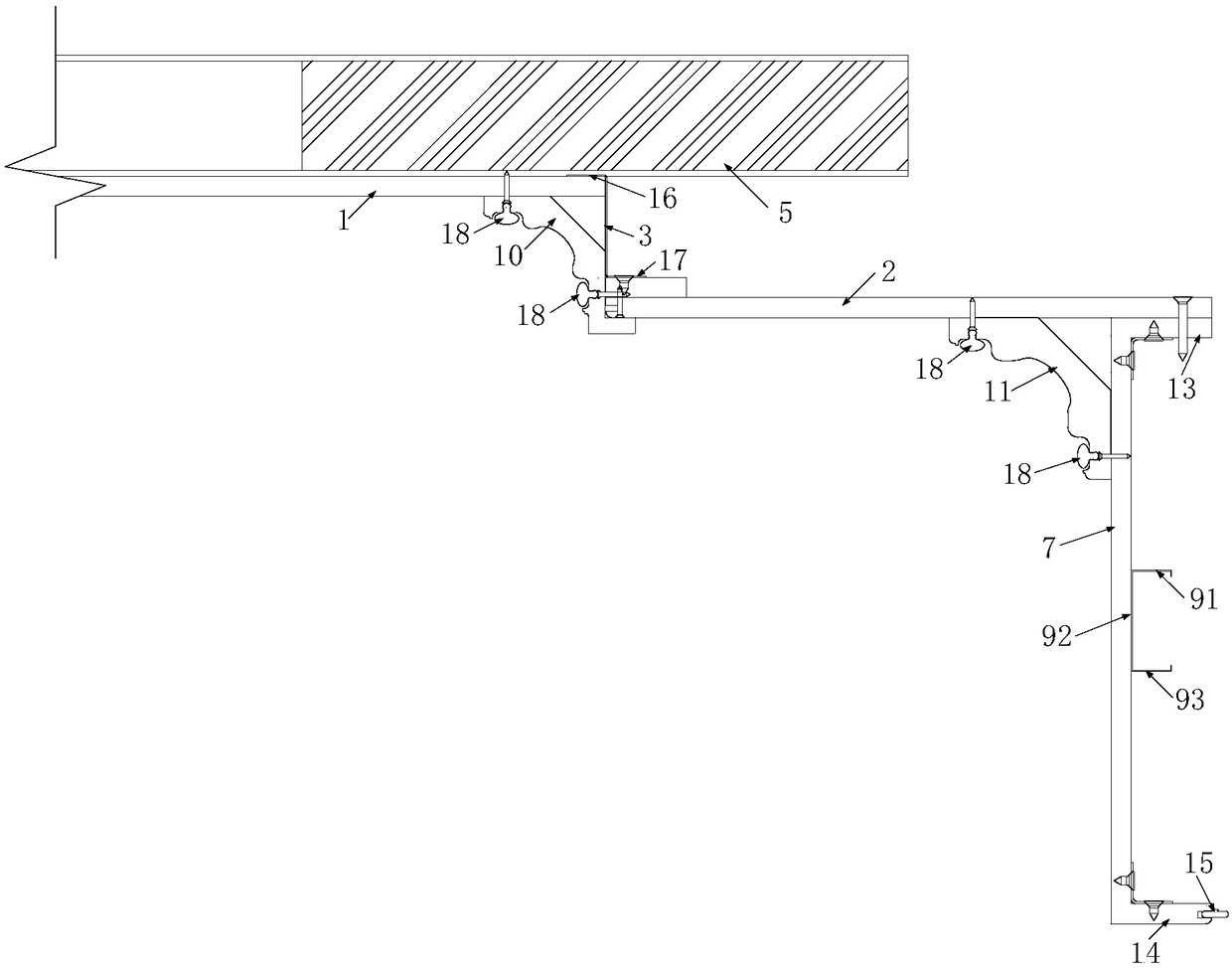
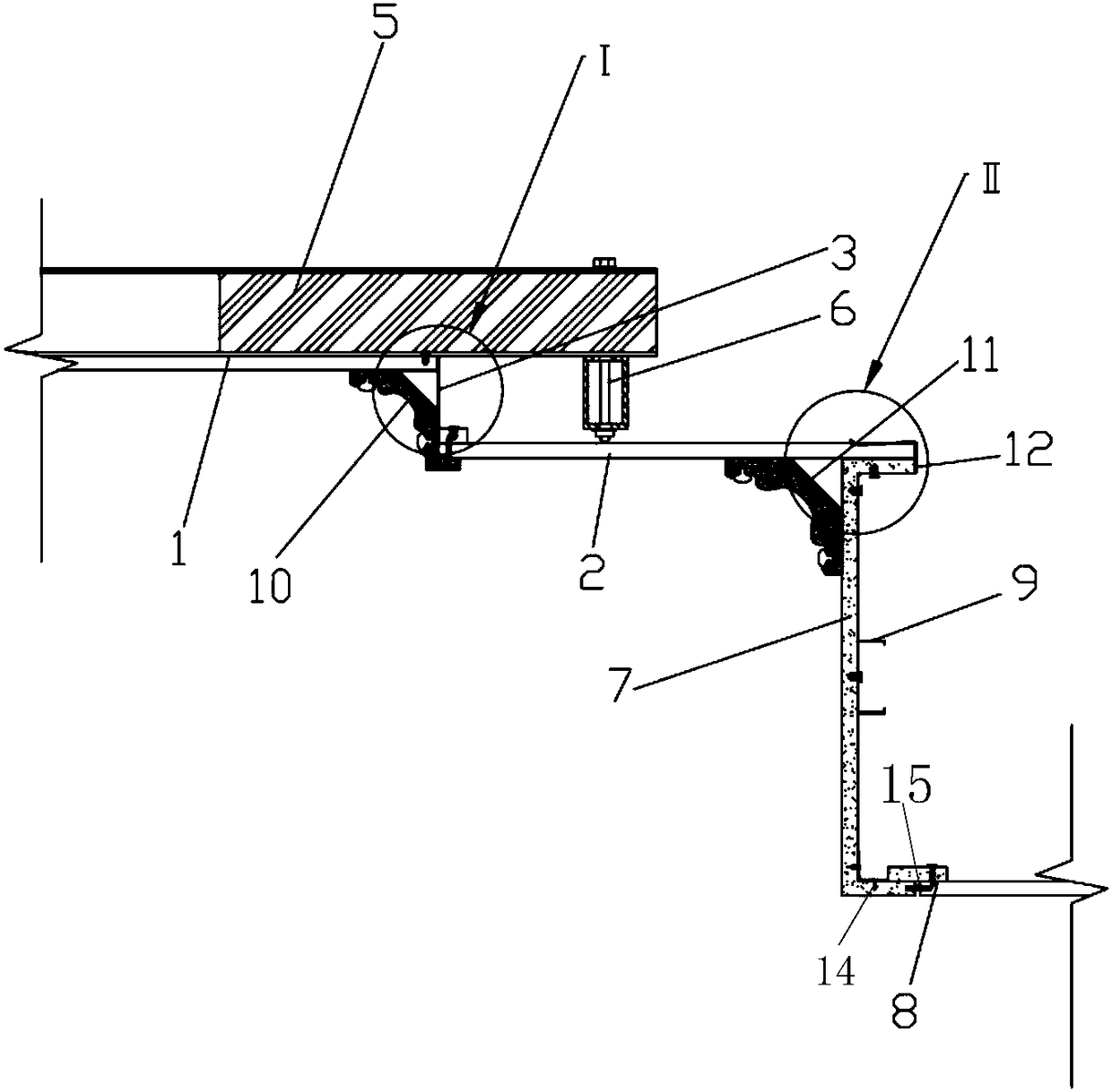
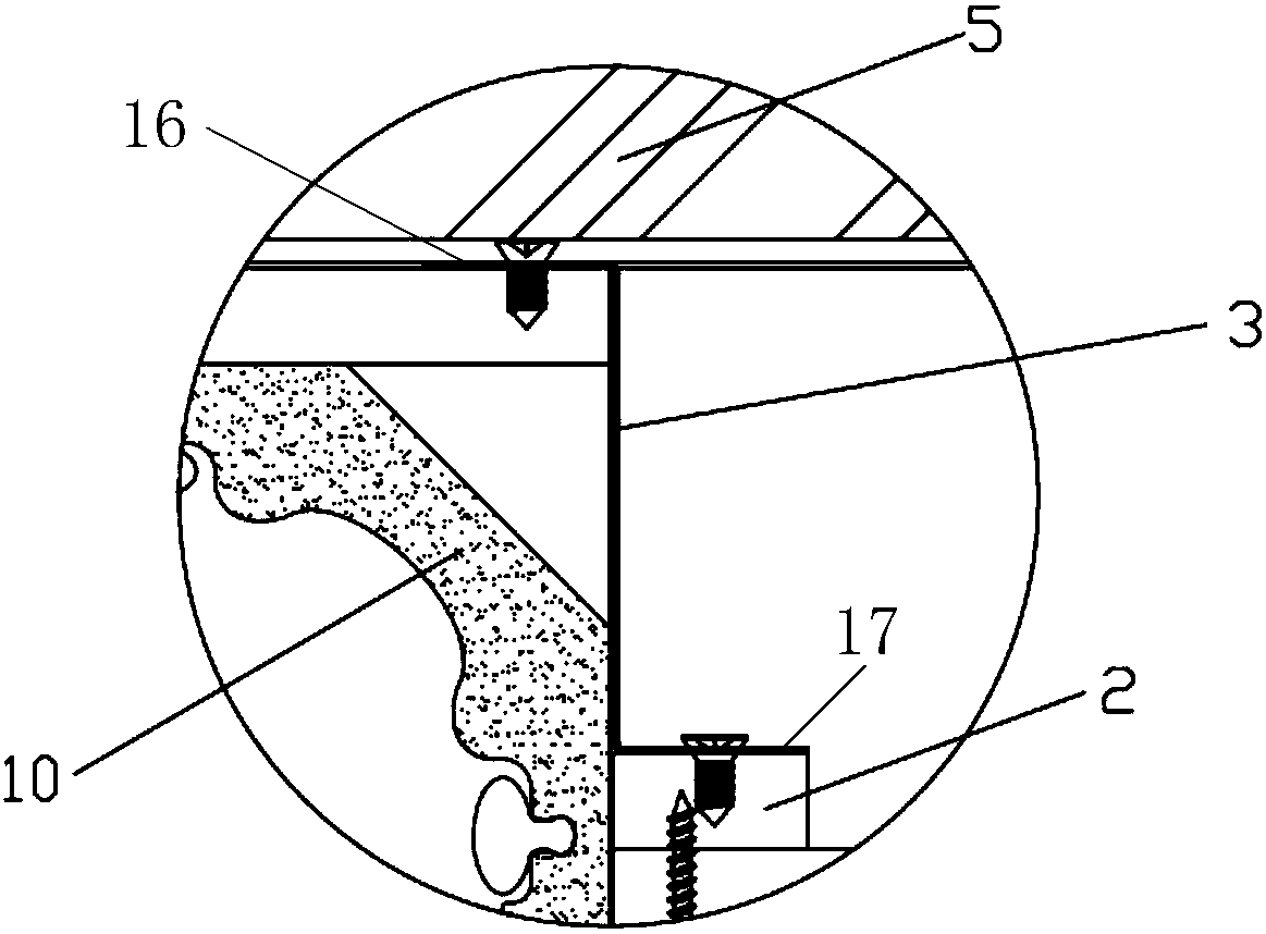
[0025] figure 1 A schematic diagram of the first structure of the European-style drop-down ceiling provided for an optional embodiment of the present invention, figure 2 The second structural schematic diagram of the European-style drop-down ceiling provided for an optional embodiment of the present invention, image 3 for figure 2 Partial enlarged view of middle Ⅰ, Figure 4 for figure 2 Partial enla...


PUM


Abstract

The invention discloses a European style lay-in ceiling and a mounting method. The European style lay-in ceiling comprises two oppositely arranged wall spaces, a primary top plate, a vertical plate and a secondary top plate which are sequentially connected as well as a vertical frame plate and a tertiary top plate which are vertically connected, wherein the primary top plate is higher than the secondary top plate, and the primary top plate and the secondary top plate are respectively arranged at the two sides of the vertical plate; the primary top plate is arranged on the two wall spaces; thevertical frame plate is arranged at one end, far away from the vertical plate, of the secondary top plate, and the vertical frame plate is lower than the secondary top plate; and the tertiary top plate extends toward a direction far away from the secondary top plate. The mounting method of the European style lay-in ceiling is used for mounting the European style lay-in ceiling. The European stylelay-in ceiling and the mounting method which are provided by the invention have the advantages that structural design is novel, structure is simple, mounting is convenient, a mounting period is short,rapid mounting of the European style lay-in ceiling is guaranteed, destruction on the original concrete of the top surface is reduced, environmental cleanliness of a construction site is improved, and labor intensity is reduced.

Description

technical field [0001] The invention relates to the technical field of architectural decoration, in particular to a European-style step-down suspended ceiling and an installation method. Background technique [0002] The suspended ceiling plays a decorative role on the top of the interior building and is an indispensable part of interior decoration. [0003] In the prior art, three-level ceilings are more commonly used in home decoration ceilings, especially for home decoration simple European-style ceilings with two or more layers of top lines, often using three-level ceilings to express the layering of the top space. In the process of realizing the invention, the inventor found that the above-mentioned three-level suspended ceiling has the following disadvantages: first, the weight of the three-level suspended ceiling is relatively large, and the damage to the original concrete on the top surface caused by hanging the three-level suspended ceiling with a hanging rod is rel...

Claims


Application Information

Patent Timeline
Patent Type & Authority Applications(China)
IPC IPC(8): E04B9/30E04B9/06E04B9/22E04G21/14
CPCE04B9/06E04B9/22E04B9/30E04G21/14
Inventor 王瑾周东珊钟诚步挺薛猛鄢凌云郑波波
Owner ZHEJIANG YASHA DECORATION
Features
  • Generate Ideas
  • Intellectual Property
  • Life Sciences
  • Materials
  • Tech Scout
  • Unparalleled Data Quality
  • Higher Quality Content
  • 60% Fewer Hallucinations
Learn More