LED ceiling lamp with optical lens cover

A technology of LED ceiling lamp and optical lens, which is applied in the field of LED lighting, can solve the problems of increasing labor cost, increasing assembly difficulty, increasing material cost, etc., and achieves the effect of improving heat dissipation effect, not increasing cost, and reducing processing and assembly difficulty

Inactive Publication Date: 2018-07-03
罗周连
View PDF0 Cites 1 Cited by
  • Summary
  • Abstract
  • Description
  • Claims
  • Application Information

AI Technical Summary

Problems solved by technology

Although this design can make the angle larger, it will be poor in terms of heat dissipation, because its heat dissipation cross-sectional area is smaller than that of ordinary LED bulbs; in addition, making multiple aluminum light panels will increase the cost of materials, and it will also be difficult in the assembly stage. Will increase the difficulty of assembly, thereby increasing labor costs

Method used


Image

  • LED ceiling lamp with optical lens cover
  • LED ceiling lamp with optical lens cover
  • LED ceiling lamp with optical lens cover

Examples


Embodiment 1

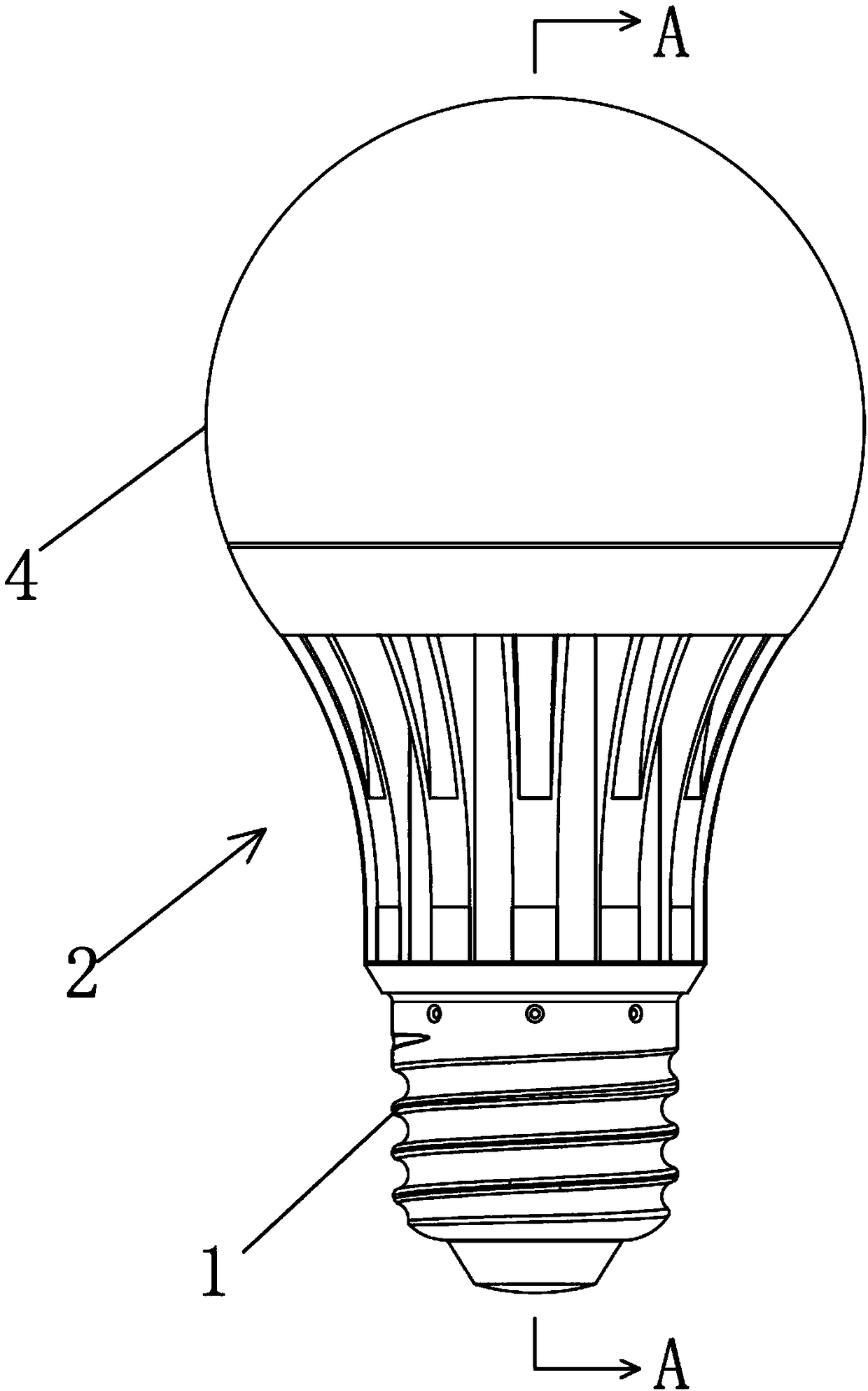
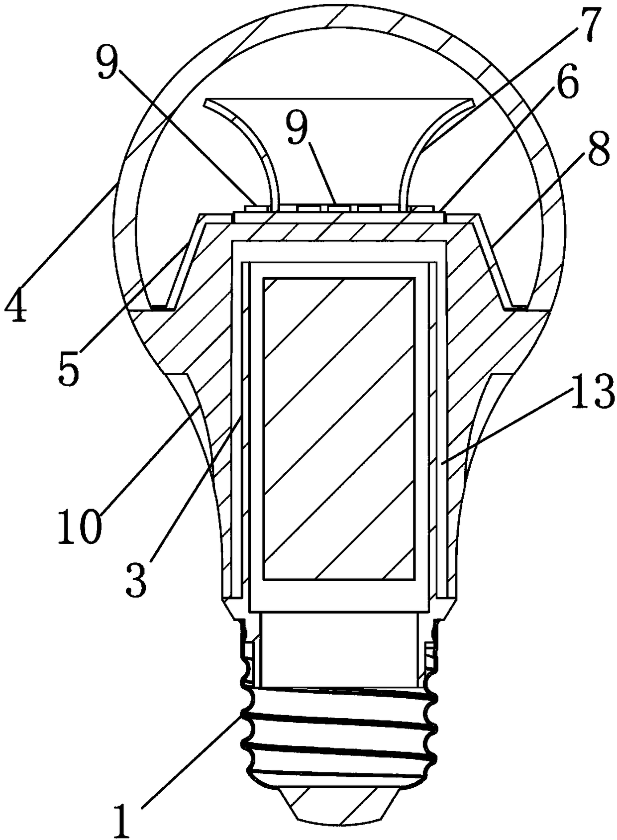
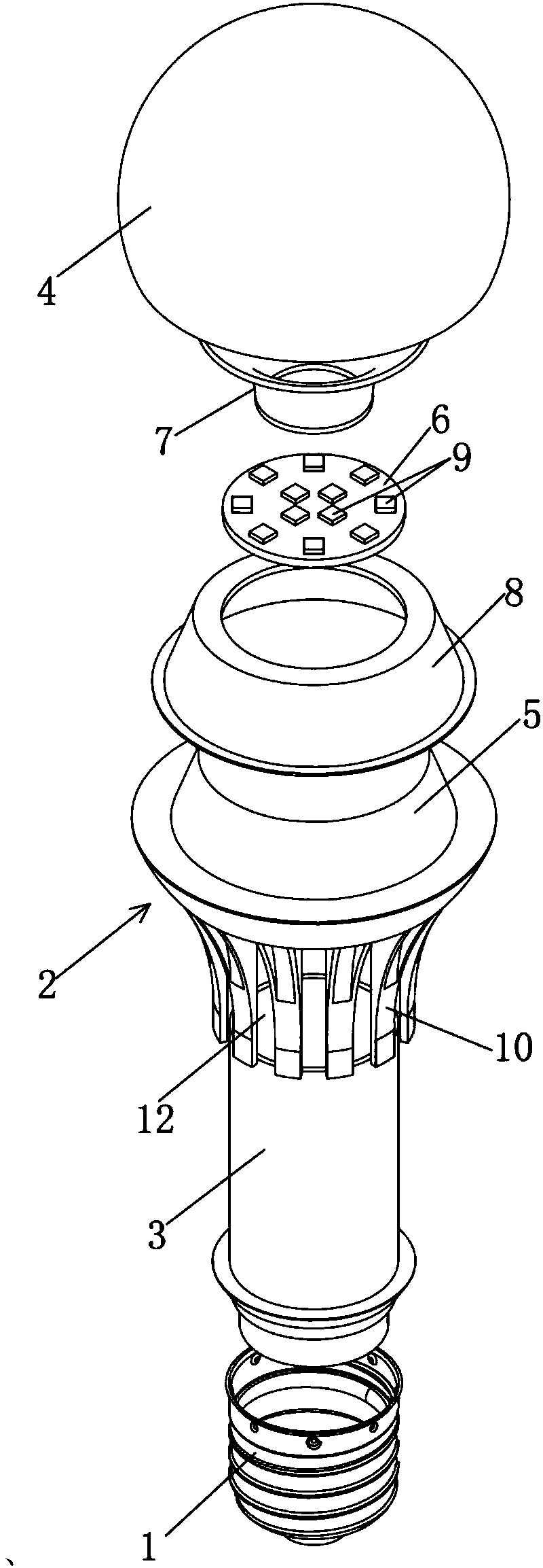
[0040] Embodiment 1: as figure 1 As shown in ~7, an LED ceiling lamp with an optical lens cover includes a lamp base 1, a lamp body 2, a power supply housing 3 and a bulb 4, and the lamp body 2 is made of an aluminum heat sink or is made of heat-conducting plastic , ceramics and other materials, the interior of the lamp body 2 is a hollow structure, the lamp body 2 and the power supply housing 3 are socketed together, and the power supply housing 3 is made of heat-conducting plastic, which can effectively dissipate heat; A lamp holder 5 protruding from the upper surface of the lamp body 2 is provided on the upper part of the lamp body 2. The longitudinal section of the bulb shell 4 is an arc larger than a semicircle, and the opening of the bulb shell 4 is installed on the periphery of the upper surface of the lamp body 2. . The shape of the outer contour of the lamp holder 5 can be any shape in polyhedron, cylinder or frustum of a cone. In this embodiment, the shape of the o...

Embodiment 2

[0045] Embodiment 2: The difference between this embodiment and Embodiment 1 is that a plurality of cup petals 14 are uniformly arranged on the upper end of the reflective cup 7 along the circumferential direction, and gaps 15 are formed between two adjacent cup petals 14 . The purpose of setting the gap is because if there is a bulb or lampshade outside the reflector cup of the LED light, on some specific bulbs or lampshades, although there is no problem with the light distribution curve of the lamp, there may be a circle of dark areas on the bulb or lampshade , set the gap 15, so that part of the light of the external LED light source 9 of the reflector 7 can pass through, and solve the dark area that may be generated on the bulb or lampshade.

Embodiment 3

[0046] Embodiment 3: The difference between this embodiment and Embodiment 2 is that the cup petals 14 are more slender, and the corresponding notch 15 is also more slender.


PUM


Abstract

The invention discloses an LED ceiling lamp with an optical lens cover. The LED ceiling lamp comprises a lamp plate and a reflection cup with the inner surface and the outer surface capable of reflecting light. The lower end of the reflection cup is arranged on the lamp plate, and LED light sources are arranged at the positions, inside and outside the lower end of the reflection cup, of the lamp plate. The lower end of the reflection cup is buckled on the lamp plate, the LED light sources are arranged at the positions, inside and outside the lower end of the reflection cup, of the lamp plate,only one lamp plate exists, it is ensured that the cost cannot be increased, machining assembling difficulty is reduced, on the other hand, the heat dissipating path is enough, and the heat dissipating effect is not affected; light emitted by the LED light source in the reflection cup passes through the inner surface of the reflection cup to be reflected and refracted, the light emit angle is increased, light emitted by the LED light source outside the lower end of the reflection cup passes through the outer surface of the reflection cup to be refracted and reflected, the light emit angle is further increased, and the large-angle emit-lighting LED lamp can be wholly formed.

Description

technical field [0001] The invention relates to the technical field of LED lighting, in particular to an LED ceiling lamp with an optical lens cover. Background technique [0002] It is difficult for ordinary LED bulbs to achieve large angles. The bulb is semicircular, so the angle basically does not exceed 200°. The existing LED ceiling lamp design with an optical lens cover is generally provided with a protruding polyhedral base on the radiator, LED lamp beads are pasted on three or more aluminum lamp panels, and then the aluminum lamps The panels are attached to the different side walls of the faceted base. Although this design can make the angle larger, it will be poor in terms of heat dissipation, because its heat dissipation cross-sectional area is smaller than that of ordinary LED bulbs; in addition, making multiple aluminum light panels will increase the cost of materials, and it will also be difficult in the assembly stage. It will increase the difficulty of assem...

Claims


Application Information

Patent Timeline
Patent Type & Authority Applications(China)
IPC IPC(8): F21S8/04F21K9/232F21V29/74F21V29/83F21Y115/10
CPCF21S8/04F21V29/74F21V29/83
Inventor 罗周连
Owner 罗周连
Why Eureka
Try Eureka