Liquid phase thermal management system for power battery

A management system and power battery technology, applied in secondary batteries, circuits, electrical components, etc., can solve problems such as poor performance and battery short circuit, and achieve reliable heating performance, sufficient cooling and heating effects

Pending Publication Date: 2018-07-03
ANHUI ANKAI AUTOMOBILE
View PDF0 Cites 4 Cited by
  • Summary
  • Abstract
  • Description
  • Claims
  • Application Information

AI Technical Summary

Problems solved by technology

Currently used power batteries are generally poor in high and low temperature performance. Therefore, thermal management of the power battery is required, that is, heating the battery at low temperature and cooling the battery at high temperature to meet the normal use of the power battery.
Commonly used thermal management systems for power batteries usually have many disadvantages. For example, air-cooling is used for cooling, and the air-conditioning air is usually blown directly into the battery box, so that the cold air directly contacts the battery. The water vapor condensation causes the battery to short circuit; if the battery is heated by the heating film, the circuit failure often occurs

Method used


Image

  • Liquid phase thermal management system for power battery
  • Liquid phase thermal management system for power battery

Examples


Embodiment 1

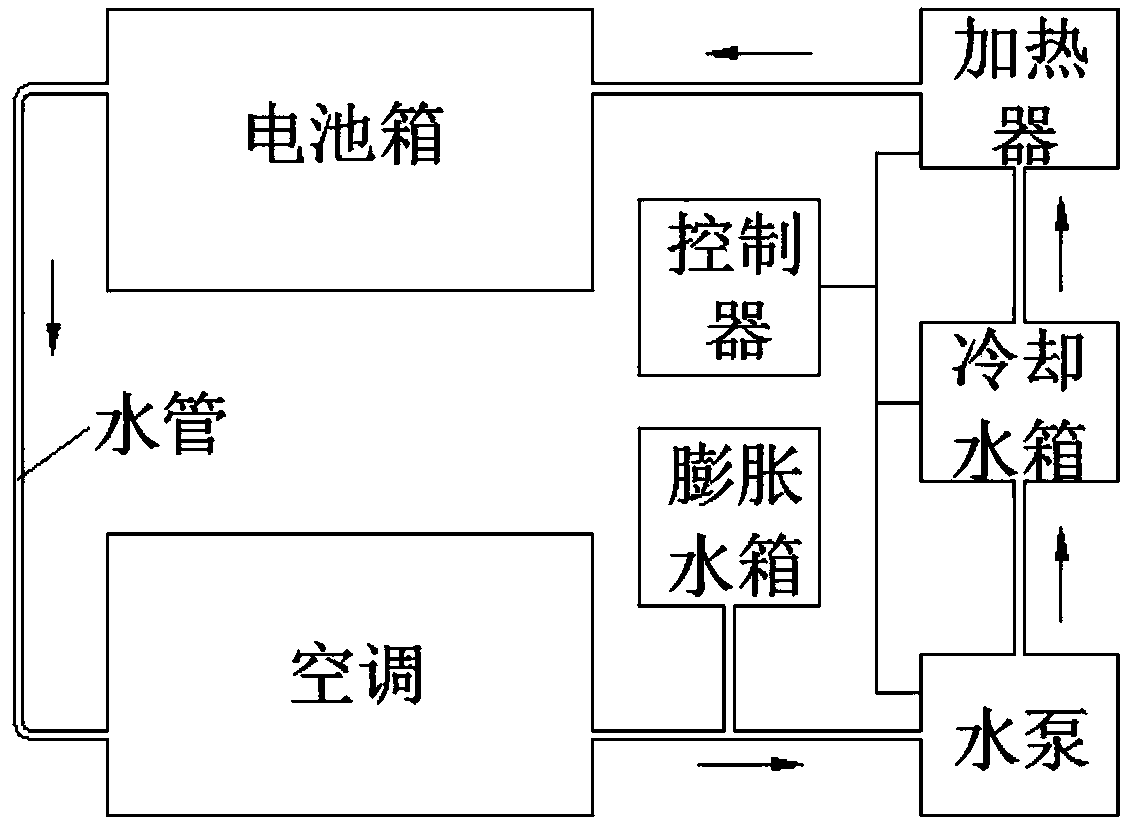
[0025] Such as figure 1 As shown, there is only one battery box in the thermal management system.

[0026] The liquid connection is as follows: the air conditioner is connected to the water pump, cooling water tank, heater, and battery box in sequence through water pipes, and the battery box is connected to the air conditioner through water pipes. The expansion tank is installed between the air conditioner and the water pump. The water tank is connected to the heater. In summer when the temperature is high and the air conditioner of the vehicle is turned on, the controller only needs to turn on the water pump to cool the battery; cooling; in winter when the temperature is low and the battery needs to be heated, the control module only needs to turn on the water pump and the heater to heat the battery.

Embodiment 2

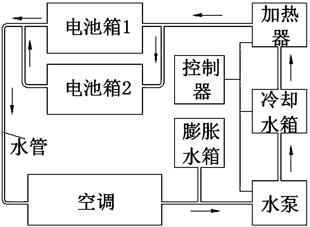
[0028] Such as figure 2 As shown, there are two battery boxes in the thermal management system.

[0029] The liquid connection is sequentially connected to the air conditioner, water pump, cooling water tank, heater, battery box, and air conditioner. The waterway between the two battery boxes is connected in parallel. The expansion tank is installed between the air conditioner and the water pump. Connected with water pump, cooling water tank and heater. In summer when the temperature is high and the air conditioner of the vehicle is turned on, the controller only needs to turn on the water pump to cool the battery; cooling; in winter when the temperature is low and the battery needs to be heated, the control module only needs to turn on the water pump and the heater to heat the battery.

[0030] Working process of the present invention is as follows:

[0031] The invention utilizes the vehicle air conditioner and the auxiliary cooling water tank to cool the battery, and us...


PUM


Abstract

The invention discloses a liquid phase thermal management system for a power battery. The liquid phase thermal management system comprises an air conditioner, a cooling water tank, a water pump, a heater, a swelling water tank, a battery box, water pipes and a controller, wherein the air conditions is sequentially connected with the water pump, the cooling water tank, the heater and the battery box through the water pipes; the battery box is connected to the air conditioner through the water pipe; the swelling water tank is arranged between the air conditioner and the water pump; and the controller is connected with the water pump, the cooling water tank and the heater respectively through wires. According to the liquid phase thermal management system, the battery is refrigerated by virtueof the complete machine air conditioner and the auxiliary cooling water tank and is heated by virtue of a heater, so that the energy resources of a complete machine can be adequately utilized, the refrigeration performance and the heating performance are reliable, and the battery can be adequately cooled and heated.

Description

technical field [0001] The invention belongs to the field of new energy vehicles and relates to a liquid-phase heat management system for a power battery. Background technique [0002] At present, zero-emission electric vehicles have become the main force of urban new energy vehicles, and power batteries are used as the power source of electric vehicles. Currently used power batteries are generally poor in high and low temperature performance. Therefore, thermal management of the power battery is required, that is, heating the battery at low temperature and cooling the battery at high temperature, so that the power battery can be used normally. Commonly used thermal management systems for power batteries usually have many disadvantages. For example, air-cooling is used for cooling, and the air-conditioning air is usually blown directly into the battery box, so that the cold air directly contacts the battery. The water vapor condensation causes the battery to short circuit; ...

Claims


Application Information

Patent Timeline
Patent Type & Authority Applications(China)
IPC IPC(8): H01M10/613H01M10/615H01M10/625H01M10/6567H01M10/663
CPCH01M10/613H01M10/615H01M10/625H01M10/6567H01M10/663Y02E60/10
Inventor 李兵徐凌飞戴蕤睿丁延军侯在荣
Owner ANHUI ANKAI AUTOMOBILE
Why Eureka
Try Eureka