
A drive test terminal test system and network test method

A drive test terminal and test system technology, applied in the field of communication, can solve problems such as inability to obtain, limited relevant parameter information, inability to distinguish terminal interaction signaling, etc., and achieve the effect of improving test efficiency, stability and robustness

Active Publication Date: 2020-10-30
DATANG MOBILE COMM EQUIP CO LTD
View PDF9 Cites 0 Cited by
  • Summary
  • Abstract
  • Description
  • Claims
  • Application Information

AI Technical Summary

Problems solved by technology

After the test is completed, the base station log can be extracted and analyzed in conjunction with the test report. The relevant parameter information that can be obtained in the current automated test process is very limited, and a large number of terminal test information cannot be obtained during the analysis process, and manual testing cannot guarantee a long-term stress test for a large number of terminals.
[0004] The current test solution can only obtain the basic information of the terminal during the automated test, but cannot obtain the environmental parameters of the terminal side, and cannot perform automatic control and stress testing of multiple terminals. Closed-loop test between Evolved Packet Core), ENB (evolved base station, evolved Node B), UE (user equipment, user equipment)
[0005] In addition, in the original automated test process, there are few terminal-side environmental parameters that can be obtained in real time, and it is impossible to distinguish the interactive signaling of specified terminals. In the process of multi-user stress testing, it is impossible to analyze each terminal in detail. Unable to complete automated testing

Method used


Image

  • A drive test terminal test system and network test method
  • A drive test terminal test system and network test method
  • A drive test terminal test system and network test method

Examples


Embodiment Construction

[0039] In order to make the purpose, technical solutions and advantages of the embodiments of the present invention clearer, the technical solutions in the embodiments of the present invention will be clearly and completely described below in conjunction with the drawings in the embodiments of the present invention. Obviously, the described embodiments It is a part of embodiments of the present invention, but not all embodiments. Based on the embodiments of the present invention, all other embodiments obtained by persons of ordinary skill in the art without creative efforts fall within the protection scope of the present invention.

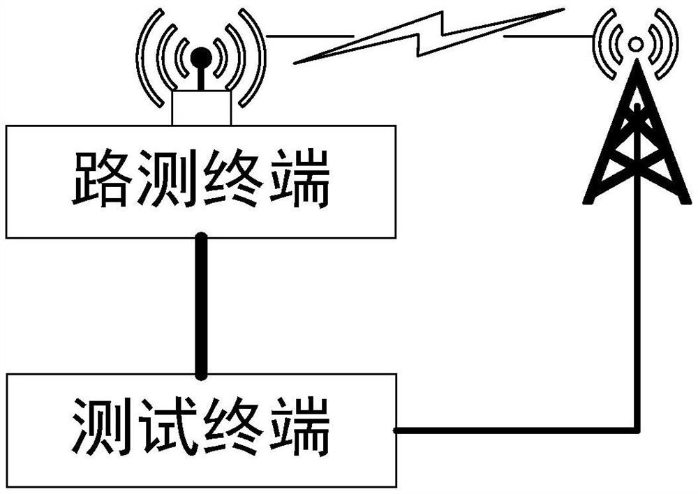
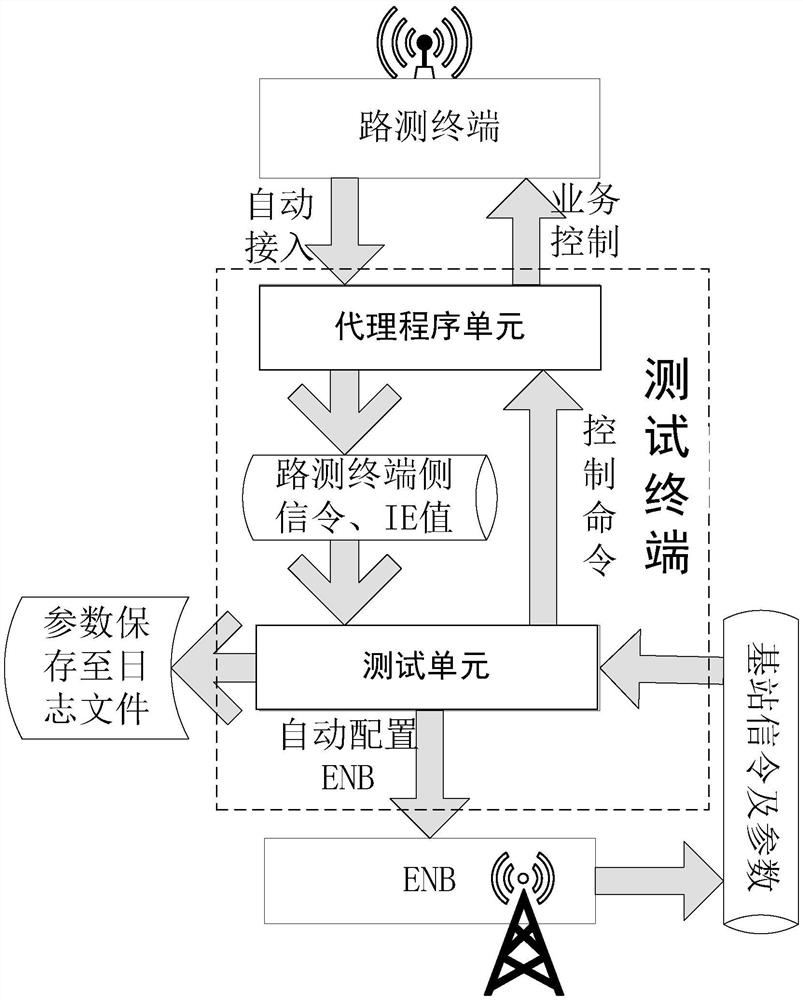
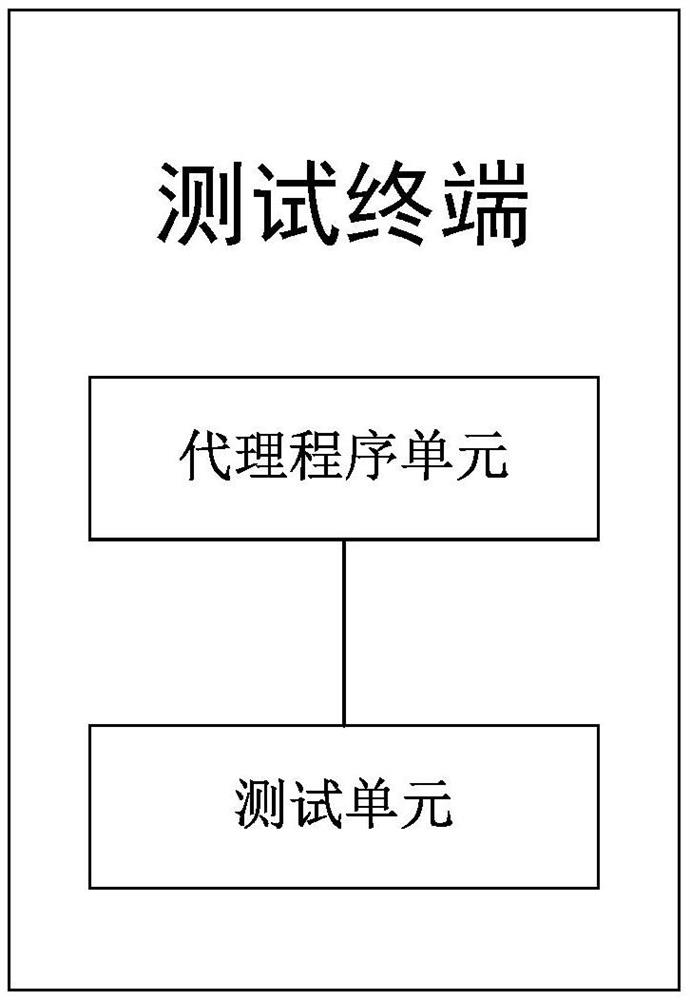
[0040] Such as figure 1 , figure 2 As shown, the present invention provides a test system for a drive test terminal, comprising: a drive test terminal communicating with a base station and a test terminal connected to the drive test terminal; the test terminal sends a control command to the drive test terminal; the drive test terminal executes t...


PUM


Abstract

The invention relates to a test system of a drive test terminal and a network test method. The system comprises a drive test terminal communicating with a base station and a test terminal connected tothe drive test terminal. The test terminal sends a control command to the drive d test terminal; the drive test terminal performs a control command to carry out communication with the base station; and the test terminal obtains an interaction message sent by the drive test terminal and obtains environment parameter information from the interaction message. According to the invention, the test terminal is used for realizing real-time and automatic access identification and control of the drive test terminal; long-term unmanned pressure testing of multiple drive test terminals is realized; andsignaling and parameters that are reported by the drive test terminals are checked and parameters like the log, terminal test signaling, and IE value during the analysis and testing processes are extracted; the stability and robustness of the test system are improved; and manual searching and collection of environment parameters by the testing staff is avoided and thus the testing efficiency is improved, and closed-loop testing of the ENB, EPC and terminal is realized.

Description

technical field [0001] The invention relates to the field of communication technology, in particular to a drive test terminal test system and a network test method. Background technique [0002] This section introduces readers to background technologies that may be related to various aspects of the present invention, and it is believed that useful background information can be provided to readers, thereby helping readers to better understand various aspects of the present invention. Accordingly, it is to be understood that the descriptions in this section are for the purposes stated above and do not constitute admissions of prior art. [0003] During the LTE (Long Term Evolution, Long Term Evolution) automated testing process, testers need to obtain a large number of environmental parameters in the test report for analyzing and locating problems. The test system can obtain and automatically configure base station parameters according to test case requirements, and conduct u...

Claims


Application Information

Patent Timeline
Patent Type & Authority Patents(China)
IPC IPC(8): H04W24/02H04W24/10
CPCH04W24/02H04W24/10
Inventor 张毅胡博刘须华邓召基
Owner DATANG MOBILE COMM EQUIP CO LTD
Learn More