Multi-rotor-wing unmanned aerial vehicle with power wing body
A multi-rotor unmanned aerial vehicle and power wing technology, applied in the field of unmanned aerial vehicles, can solve the problems of increasing the weight of the unmanned aerial vehicle, increasing the power consumption, and the power consumption of the lift, so as to reduce the weight, reduce the power consumption, Parking smooth effect
- Summary
- Abstract
- Description
- Claims
- Application Information
AI Technical Summary
Problems solved by technology
Method used
Image

Examples
Embodiment 1
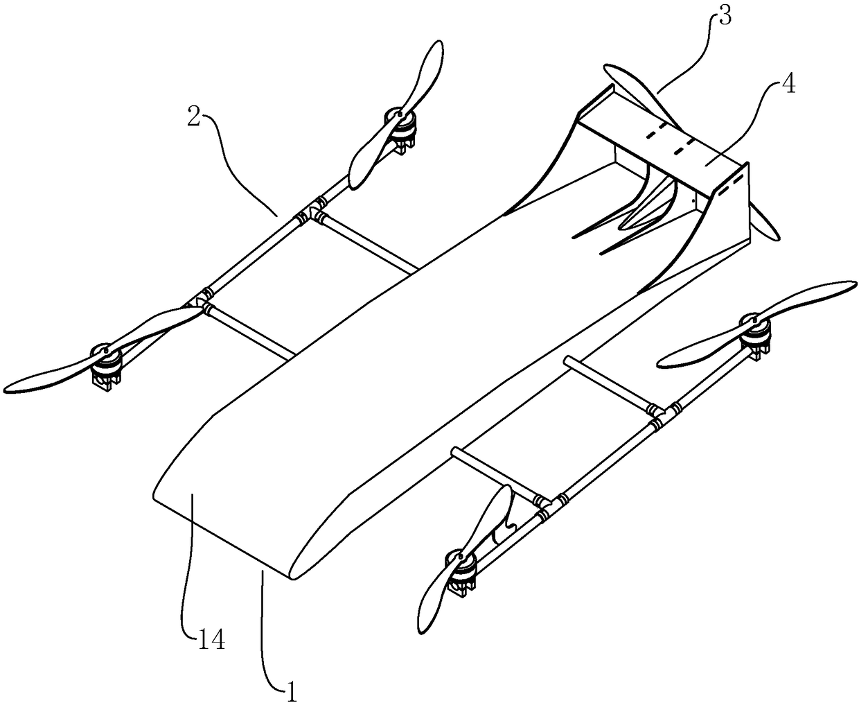
[0035] Such as figure 1 As shown, a powered wing body multi-rotor UAV includes a fuselage 1, a rotor power group 2, an empennage 4 and a fixed rotor power group 32, the rotor power group 2 is installed on both sides of the fuselage 1, and the empennage 4 is fixed on At the tail end of the fuselage 1, the fixed rotor is installed at the tail end of the fuselage 1 and behind the empennage 4. The rotor power group 2 can provide upward lift to facilitate vertical take-off and landing, while the fixed rotor power group 32 provides the forward thrust of the UAV.
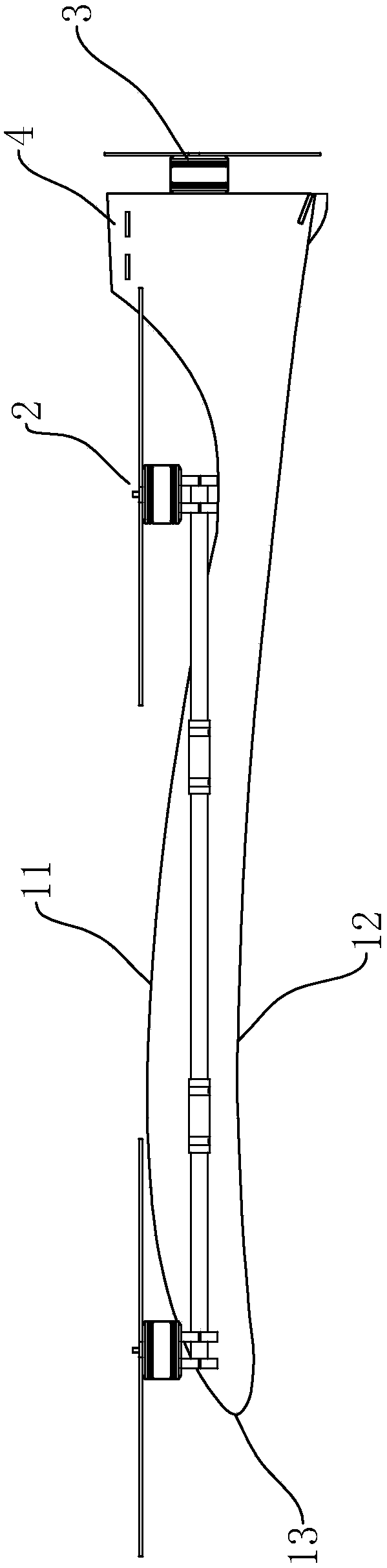
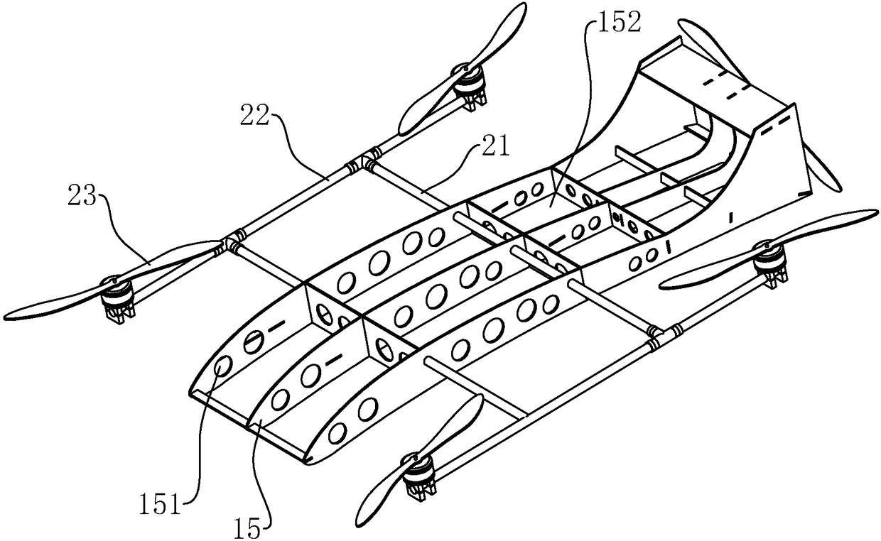
[0036] combine figure 2 , the fuselage 1 is in the shape of a wing as a whole, and the curve of the section of the fuselage 1 can directly simulate the curve of a real aircraft wing, only in a reduced proportion. combine image 3 , the fuselage 1 includes a frame 15 and a casing 14, the casing 14 covers the surface of the frame 15, and the frame 15 is bonded inside. The upper surface of the casing 14 arches upwards to...
Embodiment 2
[0041] In order to further ensure the comparative stability of the transverse installation rod 21, as Figure 4 and Figure 5 As shown, the fuselage 1 includes a fuselage main body 16 and auxiliary support parts 17 fixed on both sides of the fuselage main body 16. Compared with the fuselage main body 16, the auxiliary support part 17 is closer to the vertical installation rod 22, and is installed horizontally. The rod 21 passes through the auxiliary support part 17 to fully support the transverse installation rod 21 and also increases the space for placing items inside the fuselage 1 to a certain extent. In order not to hinder the rotation of the rotor, the auxiliary support portion 17 is located between the two adjacent rotors, and a corner for the rotor rotation is formed between the auxiliary support portion 17 and the main body 16 of the fuselage, and the space at the corner is provided for the rotation of the rotor. space.
[0042]In order to make the connection between...
Embodiment 3
[0044] combine Figure 6 , in order to park the UAV more stably, the bottom of the fuselage 1 is fixed with a support foot 5, the lower end of the support foot 5 and the tail end of the fuselage 1 form a support plane, of course, it can also be at the tail end of the fuselage 1 Design auxiliary support feet 5.
PUM
 Abstract
Description
Claims
Application Information
 - R&D Engineer
- R&D Manager
- IP Professional
- Industry Leading Data Capabilities
- Powerful AI technology
- Patent DNA Extraction
Browse by: Latest US Patents, China's latest patents, Technical Efficacy Thesaurus, Application Domain, Technology Topic.
© 2024 PatSnap. All rights reserved.Legal|Privacy policy|Modern Slavery Act Transparency Statement|Sitemap