
Dual-driving lifting type transmission system of thickener

A transmission system and dual-drive technology, applied in the field of thickeners, can solve the problems of damage to the transmission device, twisted scraper shaft and rake arm, and high concentration of underflow at the bottom, so as to ensure safety and smooth operation.

Inactive Publication Date: 2015-04-29
JINGJIN ENVIRONMENTAL PROTECTION INC
View PDF8 Cites 3 Cited by
  • Summary
  • Abstract
  • Description
  • Claims
  • Application Information

AI Technical Summary

Problems solved by technology

[0003] The thickener often breaks down in the current use process. Due to the different material particles settled by the suspension, the concentrated underflow deposition at the bottom of the thickener is sometimes greater than the discharge of the mud outlet during operation, or the material concentration is high. High, concentrated underflow particles accumulate in the tank with a large thickness, which leads to excessive resistance of the scraper rake of the thickener, causing the motor of the thickener to overload, trip and stop production, and at the same time cause damage to the transmission device, and even twist the rake shaft and arm. It is difficult to clean up the concentrated underflow solid particles deposited at the bottom of the tank due to the shutdown of production, which is the shortcoming in the use of thickeners at present.

Method used


Image

  • Dual-driving lifting type transmission system of thickener
  • Dual-driving lifting type transmission system of thickener
  • Dual-driving lifting type transmission system of thickener

Examples


Embodiment Construction

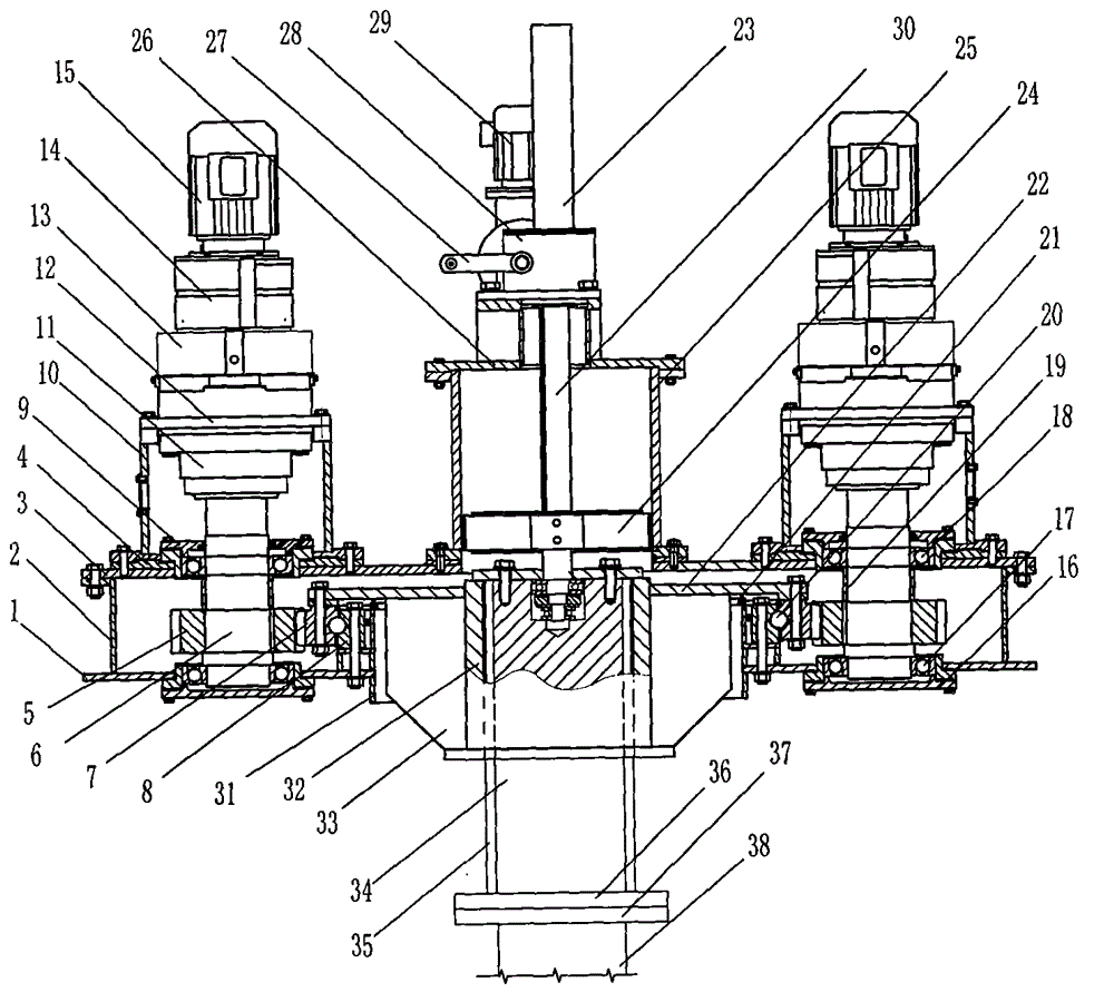
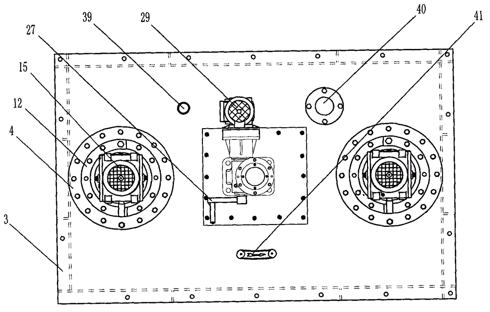
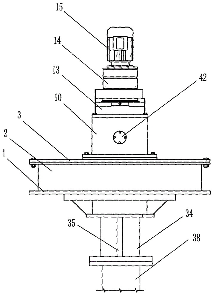
[0019] see figure 1 , figure 2 , image 3 and Figure 4 As shown, the present invention provides a dual-drive lifting transmission system for a thickener, which can be divided into five parts: the box part, the double drive part, the rotating part, the lifting part and the electrical control part, the box part, The box part is provided with a box bottom plate 1, and the outer box body plate 2 and the inner box body plate 31 are welded on the box body bottom plate 1, and the upper splint and the lower splint are welded on the inner box body plate 31. The upper splint is welded, the upper splint is provided with a polytetrafluoroethylene seal 21 to connect the large disc 22, the inner lining block 8 is installed with bolts in the upper splint and the lower splint, and the inner lining block 8 is provided with a rolling round steel ball 20 and a large gear 7 connection, the upper cover plate 3 is installed on the box body with bolts, the bracket 10 is set to weld the base 4 t...


PUM


Abstract

The invention relates to a dual-driving lifting type transmission system of a thickener. The transmission system comprises five parts: a box body part, a dual-driving part, a rotating part, a lifting part and an electrical control part; the box body part is provided with a box body bottom plate which is welded with an external box body plate and an inner box body plate, and an upper bearing and a lower bearing are arranged in the box body; dual driving refers to a mode that left and right symmetrical pinions drive a large gear, and a reducer base is arranged, a planetary reducer is arranged on the reducer base and is connected with a gear reducer; the rotating part is provided with a large disc, the large gear is arranged on the large disc, a sleeve is welded with a reinforcing rib which is connected with the large disc, a key groove is formed in the sleeve, a flat key is arranged in the key groove and is connected with a lifting shaft, a scraping rake is arranged under a scraping rake shaft, a lifting shaft is provided with a key groove, a flat key is arranged in the key groove and is connected with the sleeve, a lifting gear motor is connected with a worm gear and a worm to drive a transmission shaft to lift, a lock nut and a pressing nut locating block are arranged at the lower end of the transmission shaft and are connected with the transmission shaft, the transmission shaft is arranged in a support frame, an electrical control cabinet is arranged and is provided with a torque transmission transducer for automatically controlling the gear motor to overload an electrical element and an alarm device.

Description

technical field [0001] The invention relates to the field of thickeners for solid-liquid sedimentation separation equipment, and relates to a double-drive lifting transmission system for thickeners. Background technique [0002] Thickener is the main equipment for the separation of solid-liquid suspension mixture after gravity sedimentation. It is widely used in industrial production, such as the thickener used in mineral processing plants to separate concentrate and tailings from clean water; Salt mud settling tank, which settles and separates brine and salt mud; separation of red mud from dissolution dilution liquid in alumina plant, concentration of waste water in sewage treatment plant and water purification plant, separation of leaching slag in hydrometallurgical industry, purification and separation of wet phosphoric acid, etc. Thickener equipment is widely used. Its working principle is to use the density difference between liquid and solid particles to generate relat...

Claims


Application Information

Patent Timeline
IPC IPC(8): B01D21/18
Inventor 姜桂廷杨名杰张大伟柳宝昌
Owner JINGJIN ENVIRONMENTAL PROTECTION INC
Learn More