
Assembly structure of cutting teeth for slot milling machine and matched assembly of assembly structure

A technology of matching components and assembly structure, which is applied in the field of milling machine parts, can solve problems such as large impact on construction period, excessive wear of tooth seat, and harsh working conditions, so as to ensure accuracy and efficiency, ensure installation stability, and reduce maintenance cost effect

Active Publication Date: 2018-07-06
徐州利宝机械科技有限公司
View PDF3 Cites 0 Cited by
  • Summary
  • Abstract
  • Description
  • Claims
  • Application Information

AI Technical Summary

Problems solved by technology

In practical applications, the cutting teeth are directly involved in rock breaking, and the working conditions are very harsh. They are subjected to high impact and high stress, so that the cutting teeth continuously impact the tooth seat during the working process, causing the mounting holes of the cutting teeth on the tooth seat to wear and deform continuously. When the deformation is greater than a certain value, the tooth seat needs to be trimmed, and trimming takes a lot of time, which has a great impact on the construction period
[0003] In order to avoid the excessive wear of the tooth seat and improve its working life, the existing technology puts forward higher requirements on the material and heat treatment of the tooth seat, and in order to avoid the adverse effect of the fit clearance between the cutting teeth and the mounting hole of the tooth seat at the initial stage of installation (The larger the gap, the greater the impact of the cutting teeth on the mounting hole of the tooth seat, and the faster the wear). The production cost of the wheel will increase a lot, and its service life is still not ideal
In order to change the above problems, the existing technology uses a U-shaped gear sleeve between the gear seat and the cutting teeth. When the U-shaped gear sleeve is worn out, it can be replaced directly. Although this can prolong the life of the working device, the tooth base and the U-shaped There will be impact and wear between the gear sleeves, and the processing of the gear base and the U-shaped gear sleeve is more difficult; once the mounting hole on the gear base for assembling the U-shaped gear sleeve is worn, it will be more difficult to repair

Method used

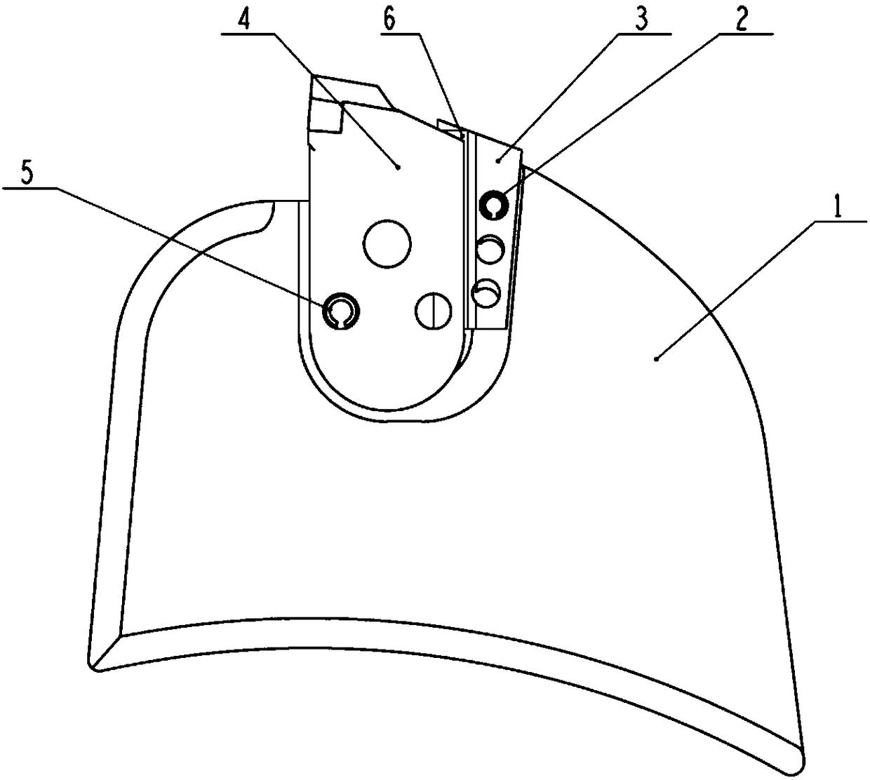

Image

  • Assembly structure of cutting teeth for slot milling machine and matched assembly of assembly structure
  • Assembly structure of cutting teeth for slot milling machine and matched assembly of assembly structure
  • Assembly structure of cutting teeth for slot milling machine and matched assembly of assembly structure

Examples


Embodiment Construction

[0084] In order to more clearly illustrate the embodiments of the present invention or the technical solutions in the prior art, the specific implementation manners of the present invention will be described below with reference to the accompanying drawings. Obviously, the accompanying drawings in the following description are only some embodiments of the present invention, and those skilled in the art can obtain other accompanying drawings based on these drawings and obtain other implementations.

[0085] In order to make the drawing concise, the parts related to the present invention are only schematically shown in each drawing, and they do not represent the actual structure of the product. In addition, to make the drawings concise and easy to understand, in some drawings, only one of the components having the same structure or function is schematically shown, or only one of them is marked. Herein, "a" not only means "only one", but also means "more than one". In this arti...


PUM


Abstract

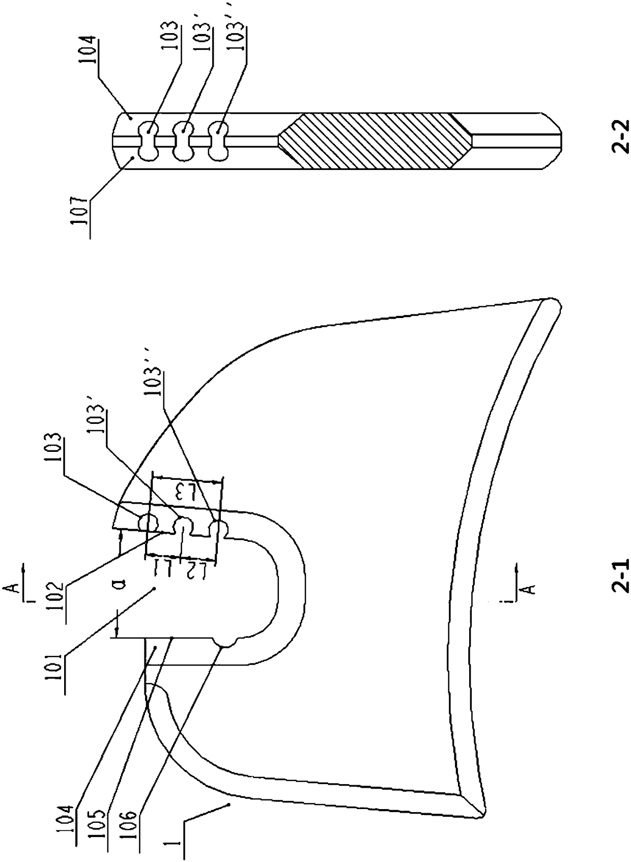
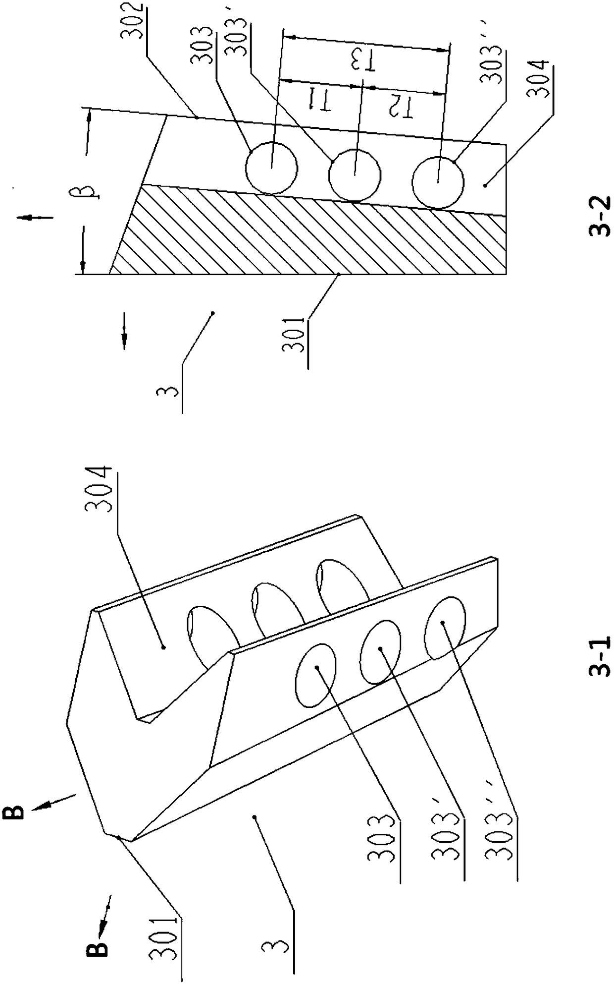
The invention discloses an assembly structure of cutting teeth for a slot milling machine and a matched assembly of the assembly structure. The assembly structure comprises the cutting teeth, a toothholder, a wedge block, a first connecting part and a second connecting part, wherein the tooth holder is provided with a U-shaped-like groove which is used for accommodating the cutting teeth, the wedge block is clamped between the side walls of the cutting teeth and the side wall of the U-shaped-like groove, first concave and convex cooperation structures are arranged at the contact portion of the cutting teeth and the tooth holder, second concave and convex cooperation structures are arranged at the contact portion of the wedge block and the tooth holder, third concave and convex cooperationstructures are arranged at the contact portion of the wedge block and the cutting teeth, the first concave and convex cooperation structures are connected through the first connecting part, and the second concave and convex cooperation structures are connected through the second connecting part. By means of the assembly structure of the cutting teeth for the slot milling machine and the matched assembly of the assembly structure, the connecting fastness of the cutting teeth and the tooth holder is guaranteed, the machining precision of the cutting teeth and the U-shaped-like groove of the tooth holder is improved, and the machining difficulty of the cutting teeth and the U-shaped-like groove of the tooth holder is lowered; mutual close cooperation of the parts is guaranteed, the impact and wear of the U-shaped-like groove during the cutting teeth work are lowered, and thus the service life of the tooth holder is prolonged; the maintenance cost of the tooth holder is reduced.

Description

technical field [0001] The invention relates to the technical field of slot milling machine components, in particular to an assembly structure of cutting teeth for a slot milling machine and its supporting components. Background technique [0002] As a relatively advanced equipment for basic construction at present, the slot milling machine is being used more and more. It relies on the rotation of the milling wheel for rock breaking operations. The milling wheel of the slot milling machine is usually welded with multiple tooth seats. The mounting hole for installing the cutting teeth, the mounting hole is usually U-shaped. In practical applications, the cutting teeth are directly involved in rock breaking, and the working conditions are very harsh. They are subjected to high impact and high stress, which makes the cutting teeth constantly impact the tooth seat during the working process, causing the mounting holes of the cutting teeth on the tooth seat to wear and deform con...

Claims


Application Information

Patent Timeline
Patent Type & Authority Applications(China)
IPC IPC(8): E02F5/02E02F5/08E02F3/22
CPCE02F3/22E02F5/02E02F5/08Y02P70/10
Inventor 吴兴丛
Owner 徐州利宝机械科技有限公司
Learn More