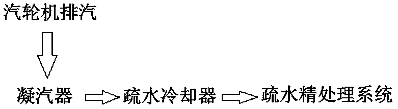
Turboset condenser

A steam turbine unit and condenser technology, which is applied to steam/steam condensers, heat exchanger shells, lighting and heating equipment, etc., can solve the problem of affecting the space layout of the steam turbine unit, high cost of operation of the steam turbine unit, site and equipment investment There are many problems, and the effect of heat exchange cooling and cooling is obvious, the effect of cooling and cooling is improved, and the stability is ensured.

Active Publication Date: 2018-07-06
DONGFANG TURBINE CO LTD
View PDF7 Cites 1 Cited by
  • Summary
  • Abstract
  • Description
  • Claims
  • Application Information

AI Technical Summary

Problems solved by technology

This is especially common with high back pressure steam turbine units. Specifically, in order to realize energy saving and consumption reduction of power plants and increase economic benefits, high back pressure steam turbine units usually use the condenser as the return water heating of the heat network, that is, through the condenser to The steam exhausted by the steam turbine is used to heat the hot water in the heating network to a predetermined temperature, so as to realize the technical purpose of reusing the waste heat of the steam exhausted by the steam turbine; there is no doubt that this will cause the condensed water condensed by the condenser The temperature is too high to meet the technical requirements of the hydrophobic finishing system. It is necessary to install a hydrophobic cooler between the condenser and the hydrophobic finishing system so that the condensed water can be cooled according to the technical requirements before entering the hydrophobic finishing system. Cooling treatment
[0004] This technology of cooling the condensed water in the condenser by means of the intermediate hydrophobic cooler can make the cooled hydrophobic effectively meet the technical requirements of the hydrophobic fine treatment system, but it will be reduced due to the increase in equipment. Affects the spatial layout of the steam turbine unit, resulting in a large investment in site and equipment, resulting in high operating costs and insufficient economic efficiency of the steam turbine unit

Method used


Image

  • Turboset condenser
  • Turboset condenser
  • Turboset condenser

Examples


Embodiment 1

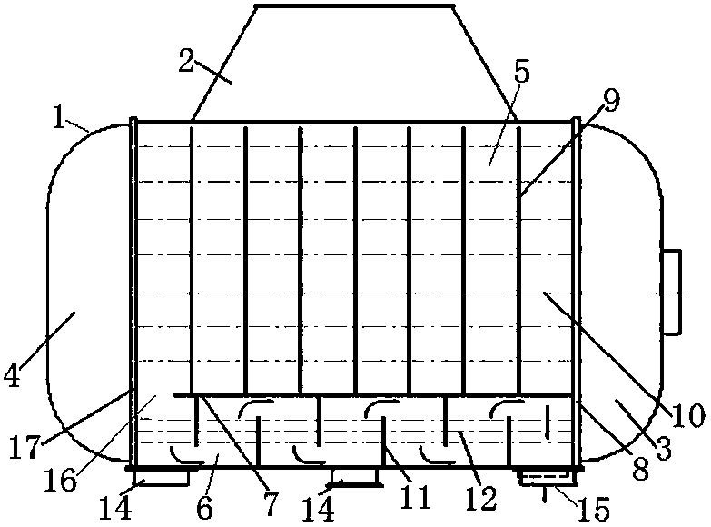
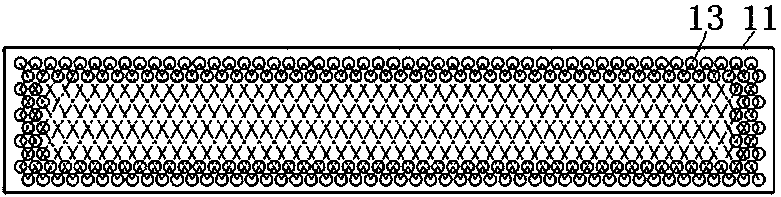
[0023] see figure 2 with image 3 As shown, the present invention comprises shell 1, and the top of this shell 1 has the throat 2 that connects steam turbine exhaust pipe, and the bottom of shell 1 has a plurality of supports 14, and the inside of shell 1 is made of end pipes on both sides. Plate—that is, the front tube plate 8 and the rear tube plate 17 are divided into a front water chamber 3, a heat exchange chamber and a rear water chamber 4, and the front water chamber 3 has a cooling water inlet and a cooling water outlet.

[0024] The heat exchange chamber is divided into an upper condensation zone 5 and a lower cooling zone 6 by partition partitions 7 in the up and down direction. The partition partition 7 is located at the lower part of the heat exchange chamber, the front end of the partition partition 7 is in sealing contact with the front tube plate 8 at the front end of the heat exchange chamber, and the rear end of the partition partition 7 is in contact with t...

Embodiment 2

[0030] see Figure 4 with Figure 5 As shown, the present invention comprises shell 1, and the top of this shell 1 has the throat 2 that connects steam turbine exhaust pipe, and the bottom of shell 1 has a plurality of supports 14, and the inside of shell 1 is made of end pipes on both sides. Plate—that is, the front tube plate 8 and the rear tube plate 17 are divided into a front water chamber 3, a heat exchange chamber and a rear water chamber 4, and the front water chamber 3 has a cooling water inlet and a cooling water outlet.

[0031]The heat exchange chamber is divided into an upper condensation zone 5 and a lower cooling zone 6 by partition partitions 7 in the up and down direction. The partition partition 7 is located at the lower part of the heat exchange chamber, the front end of the partition partition 7 is in sealing contact with the front tube plate 8 at the front end of the heat exchange chamber, and the rear end of the partition partition 7 is in contact with t...

Embodiment 3

[0037] The invention comprises a shell, the top of which has a throat connected to the exhaust pipe of the steam turbine, the bottom of the shell has a plurality of supports, and the inside of the shell is composed of end tube plates on both sides - namely the front end tube plate and the rear end tube plate. The tube sheet is divided into a front water chamber, a heat exchange chamber and a rear water chamber, and the front water chamber has a cooling water inlet and a cooling water outlet.

[0038] The heat exchange chamber is divided into an upper condensation zone and a lower cooling zone by partition partitions in the up and down direction. The partition partition is located at the lower part of the heat exchange chamber, the front end of the partition partition is in sealing contact with the front tube sheet at the front end of the heat exchange chamber, and the rear end of the partition partition is in contact with the rear tube sheet at the rear end of the heat exchange...


PUM


Abstract

The invention discloses a turboset condenser. The turboset condenser comprises a shell; a front water chamber, a heat exchange chamber and a back water chamber are arranged in the shell; the heat exchange chamber is divided into a condensation area at the upper part and a cooling area at the lower part by a partition separation plate in the up-down direction; the condensation area and the coolingarea communicate through a drainage channel in the partition separation plate; the cooling area is provided with a dewatering outlet; a heat exchange structure is arranged in the cooling area; and multiple baffle plates for baffle control of a dewatering runner between the drainage channel in the partition separation plate and the dewatering outlet are arranged in the cooling area. The turboset condenser effectively, stably and reliably integrates the functions of condensation and cooling, can be applied to a turboset to reduce the place and equipment investment of the turboset, facilitates reduction of the operation cost of the turboset, and is excellent in economy.

Description

technical field [0001] The invention relates to a condenser of a steam turbine unit. Background technique [0002] Steam is the working medium of the steam turbine. In the steam cycle process of the steam turbine unit, the steam discharged from the steam turbine needs to be condensed into water, cooled to the required temperature, and then refined. It can be seen that the steam cycle process of the steam turbine unit includes condensation, cooling, finishing and other processes. [0003] As an important component of the steam turbine unit, the condenser is used to condense the exhaust steam of the steam turbine into water by heat exchange. The existing condenser only has the function of condensing the exhaust steam of the steam turbine into water, and does not have the function of cooling the condensed water, which makes the condensed water discharged through the condenser unable to be directly discharged into the hydrophobic refinery because the temperature does not meet t...

Claims


Application Information

Patent Timeline
Patent Type & Authority Applications(China)
IPC IPC(8): F28B1/02F28B9/00F28F9/22
CPCF28B1/02F28B9/00F28F9/22F28F2009/224
Inventor 高晓亮颜强姬艳云郑雯游克华周进米沛彭宁罗明智
Owner DONGFANG TURBINE CO LTD
Why Eureka
Try Eureka