Workpiece axis positioning error compensation method for axle housing roundness and cylindricity detecting device

A technology of detection device and compensation method, which is applied to measurement devices, optical devices, instruments, etc., can solve the problems of not meeting detection conditions, not having an adjustable and movable bearing platform, and being expensive, so as to achieve the effect of increasing detection accuracy.

Active Publication Date: 2018-07-06
QILU UNIV OF TECH
View PDF9 Cites 26 Cited by
  • Summary
  • Abstract
  • Description
  • Claims
  • Application Information

AI Technical Summary

Problems solved by technology

Although the existing equipment such as roundness and cylindricity instruments have high precision and can limit the error caused by the eccentric tilt of the workpiece within a certain range, the mass of the axle housing is large and the axial span is large, which far exceeds the load limit of the rotary table and the measurement of the instrument itself. The range does not meet the detection conditions, and according to the current design structure of the heavy truck axle housing roundness and cylindricity detection device, the relative position of the sensor and the axle housing positioning is fixed, and the axle housing end does not have an adjustable and movable bearing platform. The existing technology of instrument and cylindricity instrument cannot be directly applied
At the same time, this kind of universal testing equipment is expensive and has high technical requirements, so it is difficult to apply to workshop testing

Method used


Image

  • Workpiece axis positioning error compensation method for axle housing roundness and cylindricity detecting device
  • Workpiece axis positioning error compensation method for axle housing roundness and cylindricity detecting device
  • Workpiece axis positioning error compensation method for axle housing roundness and cylindricity detecting device

Examples


Embodiment 1

[0068] A method for compensating the positioning error of a workpiece axis in an axle housing roundness and cylindricity detection device, comprising the steps of:

[0069] 1) Axle housing axis positioning eccentricity error compensation

[0070] 1) Establish the positioning model of the axle housing;

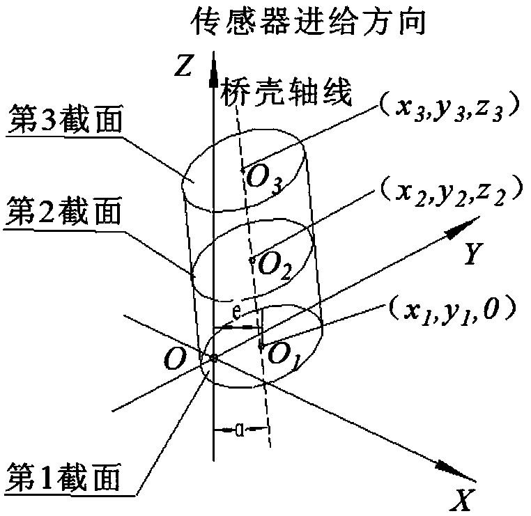
[0071] Such as figure 2 As shown, the spatial reference coordinate system is established based on the laser displacement sensor, and the XOY coordinate plane is established on the rotation plane of the laser displacement sensor. The center of rotation is the origin O, and the ordinate of the point on the XOY coordinate plane is 0; The direction is taken as the positive direction of the Z axis for mathematical modeling; the first section, the second section, and the third section are respectively set on the established axle housing positioning model; among them, the center of the first section is O 1 The coordinates are (x 1 ,y 1 , 0), the center mark O of the second cross-...


PUM


Abstract

The invention discloses a workpiece axis positioning error compensation method for an axle housing roundness and cylindricity detecting device and belongs to the field of detection. The method is characterized in that an axle housing positioning model is built, a first section, a second section and a third section are arranged on the model, and the second section and the third section are used tocorrect the first section step by step. The method specifically includes: a target section uses O as the benchmark to perform spatial translation on a circle contour where O1 is located, performing axis eccentricity compensation to obtain a section S1 after eccentricity correction, and an axis L and the section S1 are rotated a theta degree along a Z axis to obtain a section S2; the axis L and thesection S2 are rotated an alpha degree along a Y axis to allow the axis L to coincide with the Z axis so as to obtain a section S3; the section S3 and the axis L are reversely rotated theta degrees to obtain the section S4; error evaluation is performed on the section S4 to obtain real roundness errors with workpiece axis positioning eccentricity inclination errors being removed, and a constraintcondition beta is provided. The workpiece axis positioning error compensation method can compensate roundness errors and cylindricity errors caused by workpiece axis positioning eccentricity and workpiece axis positioning inclination, increase axle housing detection precision and meet ultra-precision machining requirements.

Description

technical field [0001] The invention relates to the technical field of detecting the roundness and cylindricity of an axle housing, in particular to a compensation method for a workpiece axis positioning error of an axle housing roundness and cylindricity detection device. Background technique [0002] The axle housing is a key component in the chassis of heavy-duty trucks, with an axial span of nearly 2m. Roundness and cylindricity have become key factors affecting product quality and reliability. In the past, in the production of the enterprise, the shape errors such as the roundness and cylindricity of the axle housing surface were mainly detected by contact with the manual dial indicator. It can only meet the sampling test in production. [0003] Based on the above problems, this research group has developed a roundness and cylindricity detection device for heavy truck axle housings. The structure is as follows: figure 1 As shown in the figure, 1 is the transmission mo...

Claims


Application Information

Patent Timeline
Patent Type & Authority Applications(China)
IPC IPC(8): G01B11/24
CPCG01B11/2408
Inventor 张鹏周广成单东日闫鹏
Owner QILU UNIV OF TECH
Why Eureka
Try Eureka