
Mower brake make-and-break detection device and detection method thereof

A technology of on-off detection and lawn mowers, which is applied in the field of lawn mower brakes, can solve the problems of lack of special equipment and low efficiency, and achieve the effect of simple structure and low cost

Pending Publication Date: 2018-07-06
重庆针尖内燃机部件制造有限公司
View PDF0 Cites 0 Cited by
  • Summary
  • Abstract
  • Description
  • Claims
  • Application Information

AI Technical Summary

Problems solved by technology

[0002] After the lawn mower is stopped, due to the effect of inertia, the cutter on it will continue to run, so it is necessary to install a lawn mower brake on the lawn mower. The lawn mower brake mainly includes five parts, namely the brake base 19 , flameout line 20, brake arm 21, tension spring 22 and brake block 23, wherein the brake block is connected to the brake arm by screws, and an insulating sheet is clamped between the brake block and the brake arm, as well as between the brake arm and the screw, and the flameout The line is directly connected to the screw. In order to ensure the normal operation of the lawn mower brake, it is necessary to keep the brake block and the flameout line connected (because the brake block, the screw and the flameout line are connected), the brake block and the flameout line are connected. The brake base remains in an open circuit state (because there is an insulating sheet clamped between the brake block and the brake arm), but there is currently no special equipment to detect the on-off state of the lawn mower brake. The current detection method is to directly brake the lawn mower. Assembled on the lawn mower to detect its operating status, so as to judge its on-off, this detection method is inefficient

Method used


Image

  • Mower brake make-and-break detection device and detection method thereof
  • Mower brake make-and-break detection device and detection method thereof
  • Mower brake make-and-break detection device and detection method thereof

Examples


Embodiment Construction

[0026] Below in conjunction with accompanying drawing and embodiment the present invention will be further described:

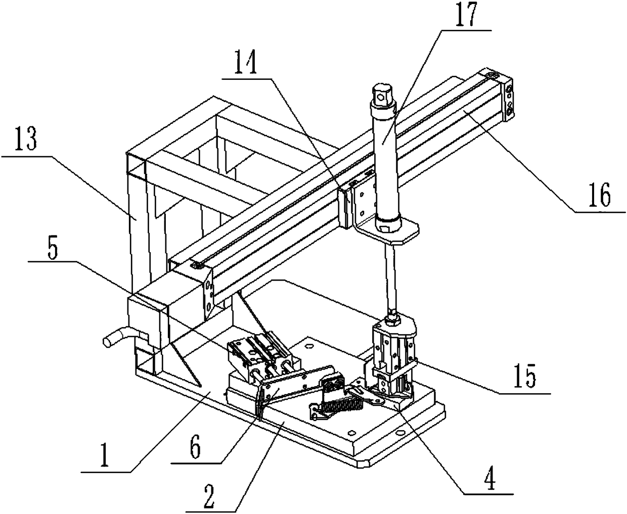
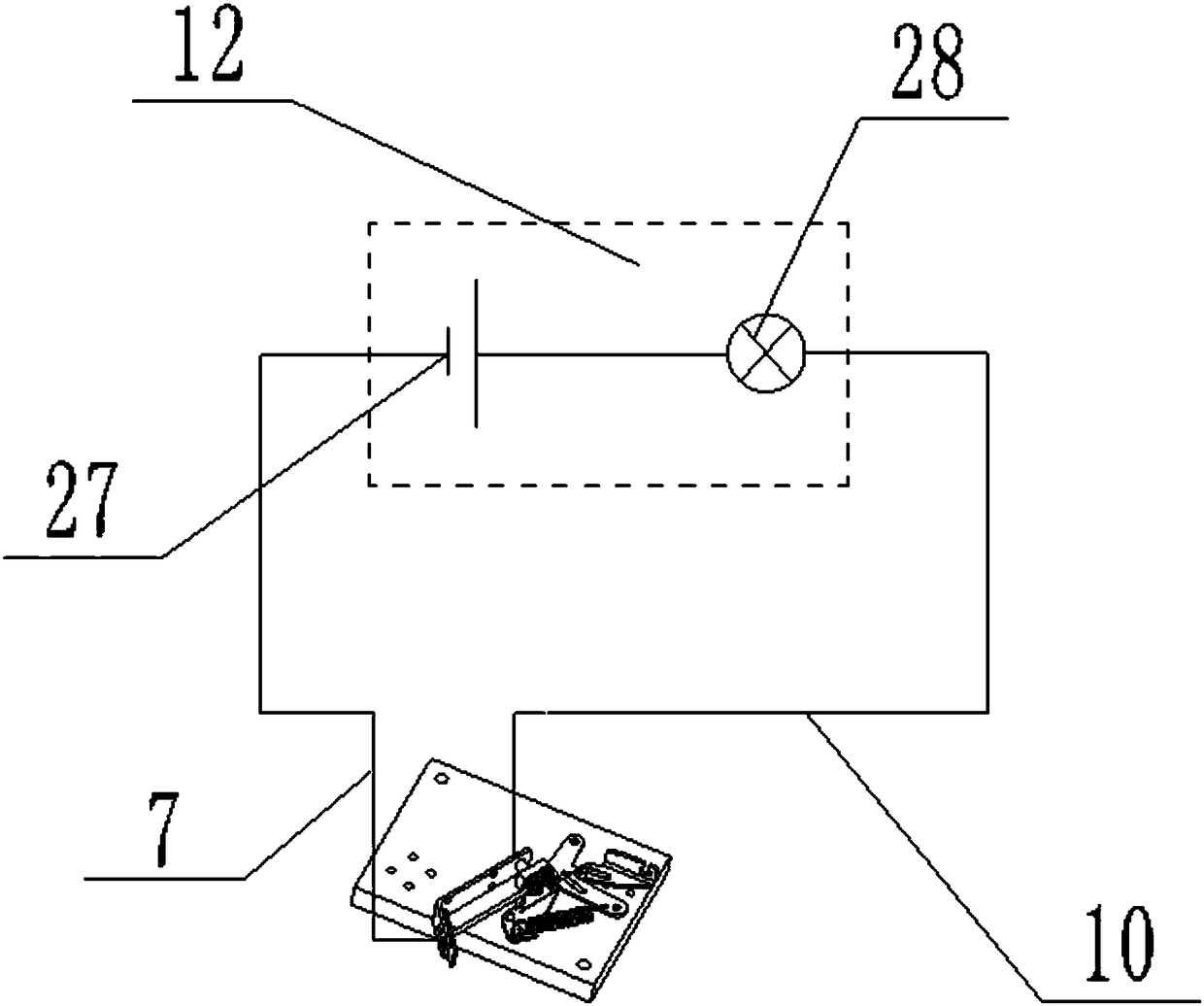
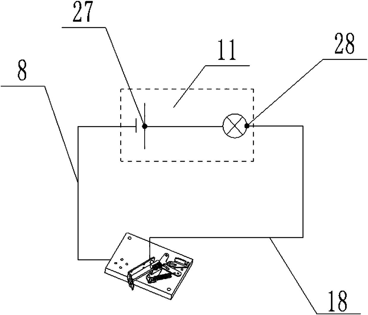
[0027] see Figure 1-4 The shown brake on-off detection device for a lawn mower includes a base 1, a brake support tray 2 is fixed on the base 1, a positioning pin 3 and a brake pad support step 4 are fixed on the brake support tray 2, A telescopic cylinder 5 is also fixed on the brake support tray 2, and a conductive piece 6 on the left side that can be in contact with the brake flameout line 20 is fixed on the telescopic cylinder 5, and the left side of the conductive piece 6 is also connected to the first wire 7 on the back. , the brake support tray 2 is connected with a second wire 8, and a connection hole is provided on the right side of the conductive sheet 6, and an insulating sleeve is fixed in the connection hole, and an insulating sleeve is fixed in the insulating sleeve to be connected with the brake. The conductive head 9 in contact with the brak...


PUM


Abstract

The invention discloses a mower brake make-and-break detection device and a detection method thereof. The device comprises a base, a brake support tray is further fixed to the base, a locating pin anda brake pad support step are fixed to the brake support tray, and a telescopic cylinder is further fixed to the brake support tray; a conducting strip of which the left side can be in contact with abrake extinction wire is fixed to the telescopic cylinder, a first wire is further connected to the back of the left side of the conducting strip, a second wire is connected to the brake support tray,a connection hole is further formed in the right side of the conducting strip, an insulation sleeve is fixed in the connection hole, a conductive head for being in contact with a brake block for braking is fixed in the insulation sleeve, a third wire and a fourth wire are connected to the tail of the conductive head, and the first wire and the third wire are connected to a first make-and-break detection device body; the second wire and the fourth wire are connected to a second make-and-break detection device body. The mower brake make-and-break detection device is simple in structure and candetect the make-and-break situation of a brake fast and conveniently, and the detection efficiency is high.

Description

technical field [0001] The invention belongs to the field of lawnmower brakes, and in particular relates to a brake on-off detection device for a lawnmower. Background technique [0002] After the lawn mower is stopped, due to the effect of inertia, the cutter on it will continue to run, so it is necessary to install a lawn mower brake on the lawn mower. The lawn mower brake mainly includes five parts, namely the brake base 19 , flameout line 20, brake arm 21, tension spring 22 and brake block 23, wherein the brake block is connected to the brake arm by screws, and an insulating sheet is clamped between the brake block and the brake arm, as well as between the brake arm and the screw, and the flameout The line is directly connected to the screw. In order to ensure the normal operation of the lawn mower brake, it is necessary to keep the brake block and the flameout line connected (because the brake block, the screw and the flameout line are connected), the brake block and th...

Claims


Application Information

Patent Timeline
IPC IPC(8): G01R31/02
CPCG01R31/50
Inventor 江鹏邹国
Owner 重庆针尖内燃机部件制造有限公司
Learn More