
Automatic wire looping machine

A wire and automatic technology, applied in the direction of line/collector parts, electrical components, circuits, etc., can solve the problems of low work efficiency, looseness, time-consuming and laborious, etc., and achieve high work efficiency, fast looping speed and simple operation Effect

Pending Publication Date: 2018-07-06
山东凯莱电气设备有限公司
View PDF0 Cites 0 Cited by
  • Summary
  • Abstract
  • Description
  • Claims
  • Application Information

AI Technical Summary

Problems solved by technology

[0002] At present, during the assembly process of high-voltage switchgear, it is necessary to connect the electrical components with wires, and the joints of the wires need to be looped first, and then the looped wire joints are placed on the wiring bolts, and finally the wiring bolts are tightened Live; now the wire joints are generally made manually, which is time-consuming and laborious, and because the workers judge with the naked eye when making the circles, the size of the circles cannot be uniform, and the error is relatively large. If the circles are large, the wiring bolts When tightening, the wire connector cannot be pressed, and it is easy to cause loosening. If the ring is relatively small, the terminal bolts cannot be penetrated, and the tightening cannot be performed. Therefore, when tightening, the ring must be adjusted for the second time. work efficiency is relatively low

Method used


Image

  • Automatic wire looping machine
  • Automatic wire looping machine
  • Automatic wire looping machine

Examples


Embodiment Construction

[0017] Below in conjunction with accompanying drawing, the present invention is described in further detail:

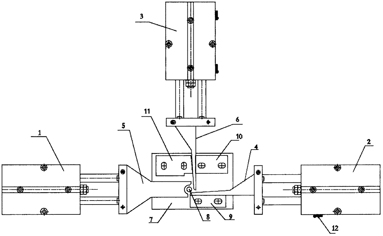
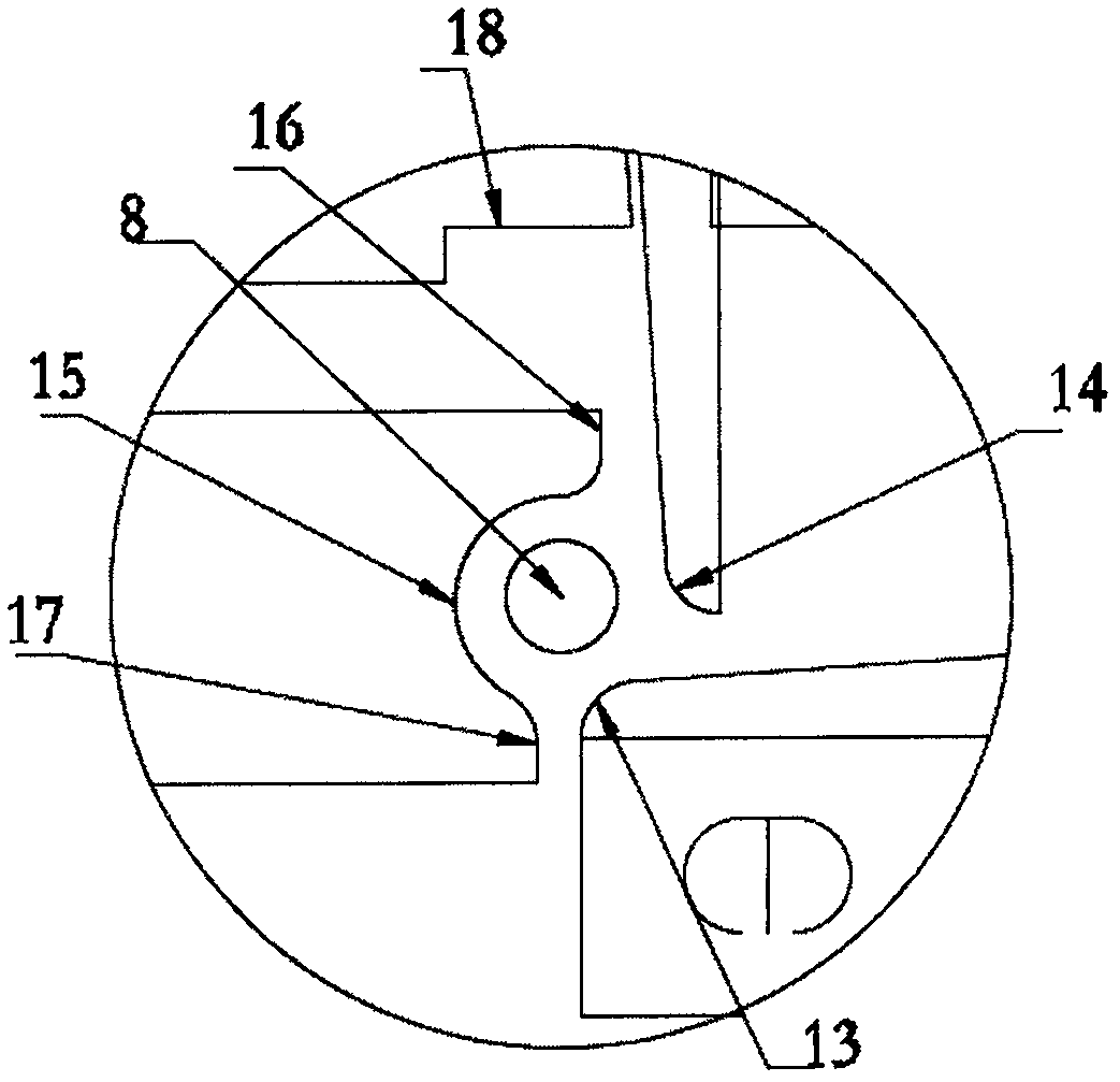
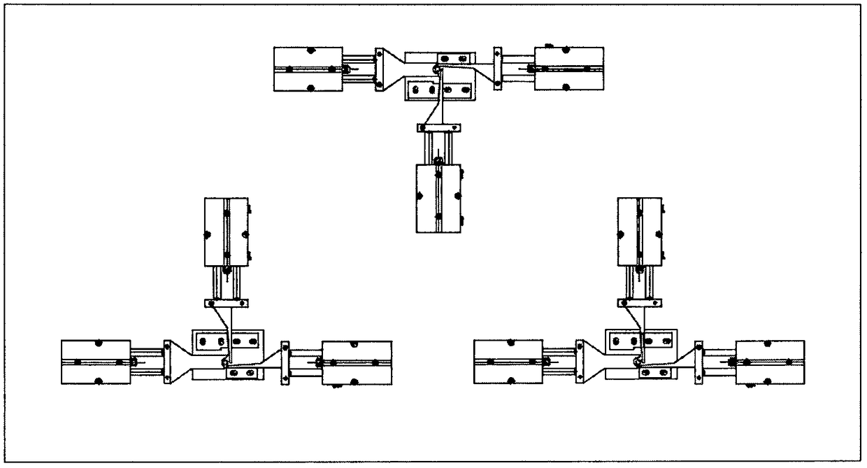
[0018] Such as figure 1 , 2 As shown, a wire automatic looping machine of the present invention includes a wire automatic looping assembly, and the wire automatic looping assembly includes a looping platform 7 and a controller, and the left and right sides and the rear side of the looping platform 7 are respectively A left cylinder 1, a right cylinder 2 and a rear cylinder 3 are provided, and a lifting cylinder is arranged under the middle part of the circle-making platform 7, and the piston rod of the lifting cylinder is connected with a cylindrical lifting cylinder whose top can rise vertically to the top of the circle-making platform 7. Column 8, the piston rod of the right cylinder 2 is connected with the lower arc pressure rod 4 that can extend to the lower right of the lifting column 8, and the piston rod of the left cylinder 1 is connected with a middle sectio...


PUM


Abstract

An automatic wire looping machine of the invention comprises an automatic wire looping component. The automatic wire looping component comprises a looping platform and a controller. A left cylinder, aright cylinder and a rear cylinder are respectively arranged on the left, right and rear sides of the looping platform. A lifting cylinder is arranged below the middle of the looping platform. The piston rod of the lifting cylinder is connected with a lifting column. The piston rod of the right cylinder is connected with a lower arc pressure rod. The piston rod of the left cylinder is connected with a middle arc pressure rod. The piston rod of the rear cylinder is connected with an upper arc pressure rod. The beneficial effects of the automatic wire looping machine are as follows: automatic wire looping is realized, and manpower is saved; the wire loop made is standard; and looping is quick and simple, and the work efficiency is greatly improved.

Description

technical field [0001] The invention relates to an automatic wire looping machine. Background technique [0002] At present, during the assembly process of high-voltage switchgear, it is necessary to connect the electrical components with wires, and the joints of the wires need to be looped first, and then the looped wire joints are placed on the wiring bolts, and finally the wiring bolts are tightened Live; now the wire joints are generally made manually, which is time-consuming and laborious, and because the workers judge with the naked eye when making the circles, the size of the circles cannot be uniform, and the error is relatively large. If the circles are large, the wiring bolts When tightening, the wire connector cannot be pressed, and it is easy to cause loosening. If the ring is relatively small, the terminal bolts cannot be penetrated, and the tightening cannot be performed. Therefore, when tightening, the ring must be adjusted for the second time. The work effic...

Claims


Application Information

Patent Timeline
IPC IPC(8): H01R43/28
CPCH01R43/28
Inventor 王张丰
Owner 山东凯莱电气设备有限公司
Learn More