Curing device for coating optical fibers with UV resin

A curing device and coating technology, which is applied to the device, coating, pre-treatment surface, etc. of the surface coating liquid, can solve the problems of increasing the energy consumption of equipment operation, increasing the cost of equipment, increasing the cost of use, etc., and achieve the curing effect. Good, cost-saving, cost-saving effect

Inactive Publication Date: 2018-07-10
昆山诺必达电子有限公司 +1
View PDF0 Cites 2 Cited by
  • Summary
  • Abstract
  • Description
  • Claims
  • Application Information

AI Technical Summary

Problems solved by technology

In the prior art, the ultraviolet light irradiation light crosslinking device mostly adopts a medium mercury lamp to generate ultraviolet light irradiation, the life of the mercury lamp is short, and with the increase of the use time, the intensity of ultraviolet light decays quickly, and it will generate a large amount of light. Heat usually needs to be equipped with high-power cooling equipment. Therefore, there are devices that use LED ultraviolet lamps as light sources in the prior art. Since the intensity of the LED is not high enough, and the optical fiber is circular, it is necessary to irradiate all surfaces. In the process, it is necessary to take into account all aspects. The LED ultraviolet lamp irradiation cross-linking equipment in the prior art mostly adopts the method of setting up multiple LED ultraviolet lamps for irradiation, so that the optical fiber can be fully irradiated.
For example, there is a way to install two LED lamps on both sides of the quartz tube through which the optical fiber passes. However, if two LED lamps are used, there will still be areas that cannot be irradiated, but if a large number of LED ultraviolet lamps are installed, the equipment cost will increase. And it will increase the energy consumption of equipment operation and increase the cost of use

Method used


Image

  • Curing device for coating optical fibers with UV resin
  • Curing device for coating optical fibers with UV resin

Examples


Embodiment Construction

[0017] In order to make the object, technical solution and advantages of the present invention clearer, the present invention will be further described in detail below in conjunction with specific embodiments. It should be understood that the specific embodiments described here are only used to explain the present invention, and are not intended to limit the present invention.

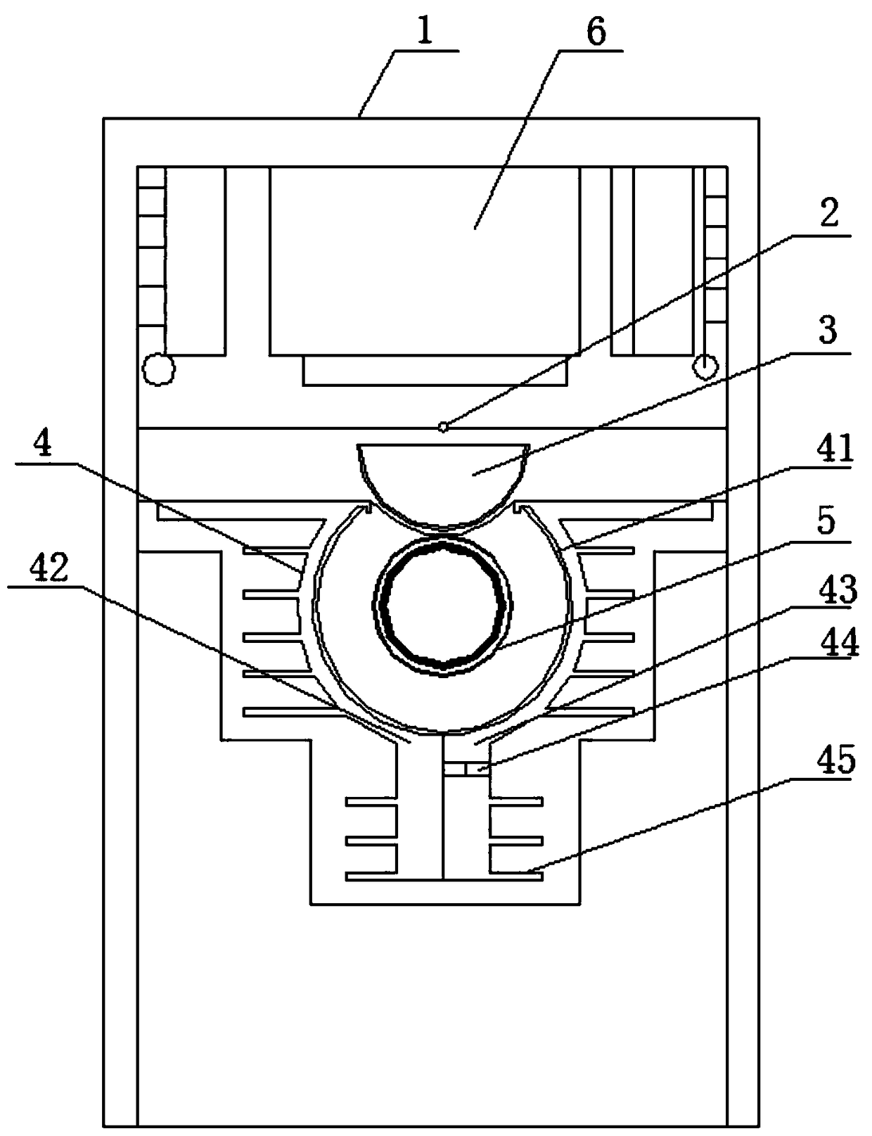
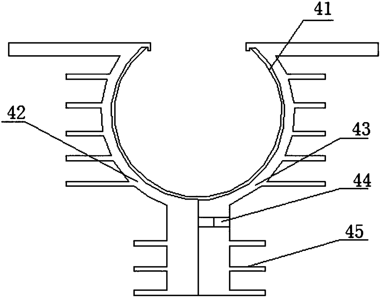
[0018] see figure 1 and figure 2 , this specific embodiment discloses a curing device for coating UV resin on an optical fiber, including a light source 2, a condenser lens 3, a condenser groove 4 and a box body 1, and the light source 2, the condenser lens 3 and the condenser The grooves 4 are arranged close to each other in turn, the condenser lens 3 is located at the front end of the light source 2, the condenser lens 3 is located at the opening of the condenser groove 4, and the condenser groove 4 is a symmetrical structure on both sides, which is feasible. In this specific embodiment, the light...


PUM


Abstract

The invention discloses a curing device for coating optical fibers with UV resin. The curing device comprises a light source, a condensing lens, a condensing trough and a tank body, wherein the lightsource, the condensing lens and the condensing trough are attached in sequence, the condensing lens is located at the front end of the light source and installed at an opening of the condensing trough, the condensing trough is of a bilateral symmetry structure, a high-reflection layer is arranged on the inner wall of the condensing trough, and light rays emitted out from the condensing lens are reflected by the high-reflection layer and then gathered at the center position of the condensing trough. The curing device has the advantages that as the condensing trough is arranged at the rear end of the condensing lens, a quartz tube is disposed into the condensing trough, and the light rays are reflected and focused to the center of the quartz tube through the condensing trough, the light intensity loss can be effectively reduced, all faces of the optical fibers can be irradiated through only one light source, power consumption is reduced accordingly, the cost is reduced, besides, the curing effect is good, less heat is generated as fewer light source is adopted, and the device of a heat dissipation is reduced in a disguised mode.

Description

technical field [0001] The invention relates to an optical fiber cross-linking device, in particular to a curing device for coating UV resin on an optical fiber. Background technique [0002] Irradiation cross-linking technology refers to the realization of cross-linking reaction of macromolecules by chemical means (such as adding cross-linking agent) or physical methods (such as irradiation), so that linear polymers become polymers with three-dimensional space network structure. technology. It has the characteristics of saving money, time and versatility, and is widely used in the field of optical fiber manufacturing. In the prior art, the ultraviolet light irradiation light crosslinking device mostly adopts a medium mercury lamp to generate ultraviolet light irradiation, the life of the mercury lamp is short, and with the increase of the use time, the intensity of ultraviolet light decays quickly, and it will generate a large amount of light. Heat usually needs to be equ...

Claims


Application Information

Patent Timeline
Patent Type & Authority Applications(China)
IPC IPC(8): B05D3/06
CPCB05D3/067
Inventor 邹小星陈蕤森
Owner 昆山诺必达电子有限公司
Why Eureka
Try Eureka