Novel PCB separator

A plate separator, a new type of technology, applied in the separation method, dispersed particle filtration, dispersed particle separation, etc., can solve the problems of unreasonable structural design of the dust collection mechanism, inability to move synchronously, and inability to cut curves, etc., to achieve the effect of dust collection and filtration Good, improve production quality, save energy consumption

Inactive Publication Date: 2018-07-10
东莞市手拉手电子科技有限公司
View PDF0 Cites 19 Cited by
  • Summary
  • Abstract
  • Description
  • Claims
  • Application Information

AI Technical Summary

Problems solved by technology

However, the existing PCB splitter still has the following deficiencies: 1. In the process of cutting the PCB board, dust will be generated. If it remains on the PCB, it will affect the quality and work of the electronic circuit. Therefore, the existing PCB splitter The machine is usually equipped with a dust collection mechanism for dust collection operations, but the structural design of the existing dust collection mechanism is unreasonable, the position of the suction part is relatively scattered, and it cannot move synchronously with the spindle cutting mechanism, resulting in small suction and poor dust collection. The efficiency is low, and it is difficult to completely remove the dust; 2. The existing PCB splitter can only cut one line at a time, and a circuit board needs to be turned and cut many times, and the curve cannot be cut

Method used


Image

  • Novel PCB separator
  • Novel PCB separator
  • Novel PCB separator

Examples


Embodiment Construction

[0032] In order to make the purpose, technical solutions and advantages of the embodiments of the present invention clearer, the technical solutions in the embodiments of the present invention will be clearly and completely described below in conjunction with the drawings in the embodiments of the present invention. Obviously, the described embodiments It is a part of embodiments of the present invention, but not all embodiments. Based on the embodiments of the present invention, all other embodiments obtained by persons of ordinary skill in the art without creative efforts fall within the protection scope of the present invention.

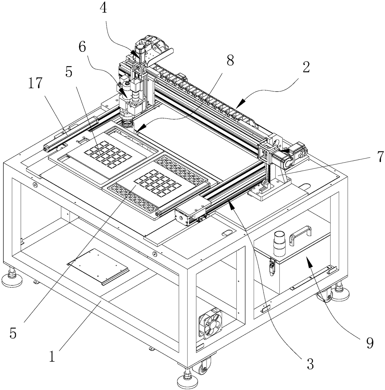
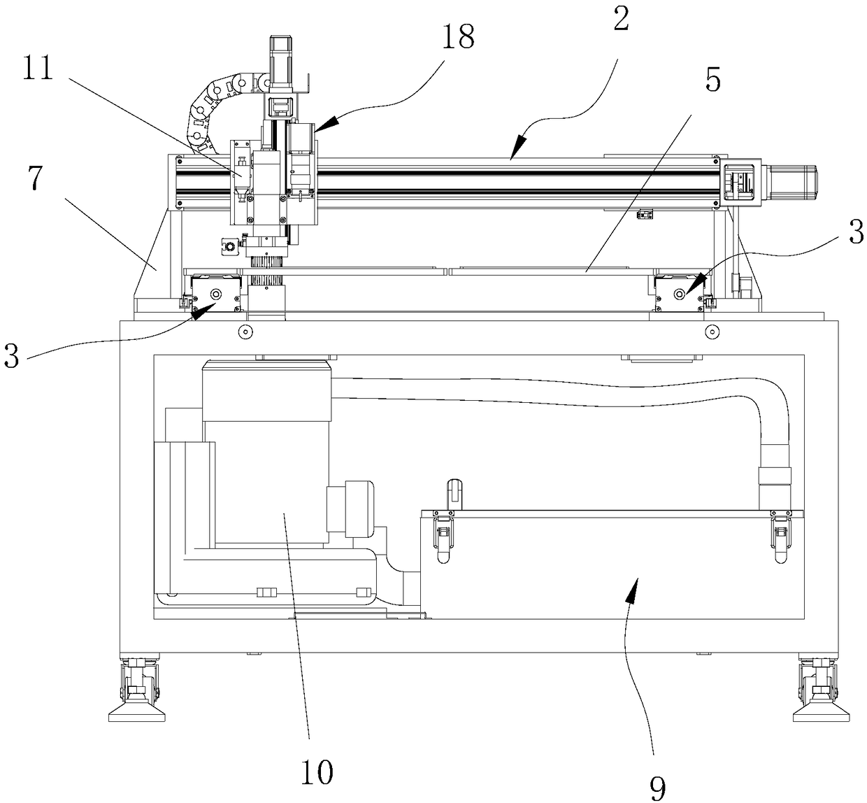
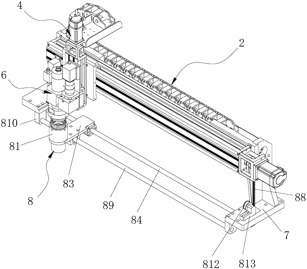
[0033] Please refer to figure 1 and figure 2, the embodiment of the present invention provides a new type of PCB splitting machine, including a frame 1, an X-axis moving mechanism 2 for driving the Z-axis moving mechanism 4 to move left and right, and a Y-axis for driving the jig tray 5 to move back and forth Moving mechanism 3, Z-axis moving m...


PUM


Abstract

The invention discloses a novel PCB separator. The novel PCB separator comprises a frame, an X-axle moving mechanism, a Y-axle moving mechanism, a Z-axle moving mechanism, a tool tray, a main shaft cutting mechanism, a linked dust sucking mechanism and a dust collection and filter mechanism; the linked dust sucking mechanism is in transmission connection with the X-axle moving mechanism, and can synchronously move along with the main shaft cutting mechanism on the X-axle moving mechanism to suck dust on PCBs on the tool tray; a dust sucking part of the linked dust sucking mechanism is connected with an inlet of the dust collection and filter mechanism through a pipe; and an outlet of the dust collection and filter mechanism is connected with an air sucker through another pipe. The novel PCB separator is reasonable in structural design, stable and reliable in operation, convenient to operate, high in machining precision, excellent in dust sucking effect and high in efficiency, can thoroughly remove the dust, and can realize linear and curve trajectory cutting. In addition, the dust collection and filter mechanism needs no disposable dust collection bag, can achieve recycling after cleaning to prevent the resource waste, and is low in cost and excellent in dust collection and filter effect.

Description

technical field [0001] The invention relates to the technical field of PCB production equipment, and more specifically relates to a novel PCB splitter. Background technique [0002] Circuit boards are necessary components in electronic products. In the production process of electronic products, circuit boards need to be divided by a splitter. PCB splitter is a kind of machine equipment that cuts off the ribs of multiple circuit boards that are set up as one to separate them into individual circuit boards. Compared with the traditional manual cutting method, it has high cutting efficiency, good safety, Reduce the labor intensity of the operator and other advantages. However, the existing PCB splitter still has the following deficiencies: 1. In the process of cutting the PCB board, dust will be generated. If it remains on the PCB, it will affect the quality and work of the electronic circuit. Therefore, the existing PCB splitter The machine is usually equipped with a dust co...

Claims


Application Information

Patent Timeline
Patent Type & Authority Applications(China)
IPC IPC(8): B26D1/12B26D5/00B26D5/02B26D7/18B26D7/26B08B15/04B01D46/24B01D46/00
CPCB01D46/2411B08B15/04B26D1/125B26D5/007B26D5/02B26D7/1863B26D7/2628B26F2210/08B01D46/58
Inventor 刘荣帅
Owner 东莞市手拉手电子科技有限公司
Why Eureka
Try Eureka