Electric shock resistant new-energy vehicle charging pile

A technology for new energy vehicles and charging piles, applied in electric vehicle charging technology, electric vehicles, charging stations, etc., can solve problems such as electric shock to the human body, and achieve the effect of ensuring charging and moving smoothly

Inactive Publication Date: 2018-07-10
郑州恒之博新能源科技有限公司
View PDF1 Cites 6 Cited by
  • Summary
  • Abstract
  • Description
  • Claims
  • Application Information

AI Technical Summary

Problems solved by technology

[0006] The invention overcomes the deficiencies of the prior art, provides a charging pile for new energy vehicles that can be automatically plugged and unplugged to avoid electric shock to the human body, and solves the problem that the existing new energy vehicles need to hold the gun body to charge and cause electric shock to the human body

Method used


Image

  • Electric shock resistant new-energy vehicle charging pile
  • Electric shock resistant new-energy vehicle charging pile

Examples


Embodiment 1

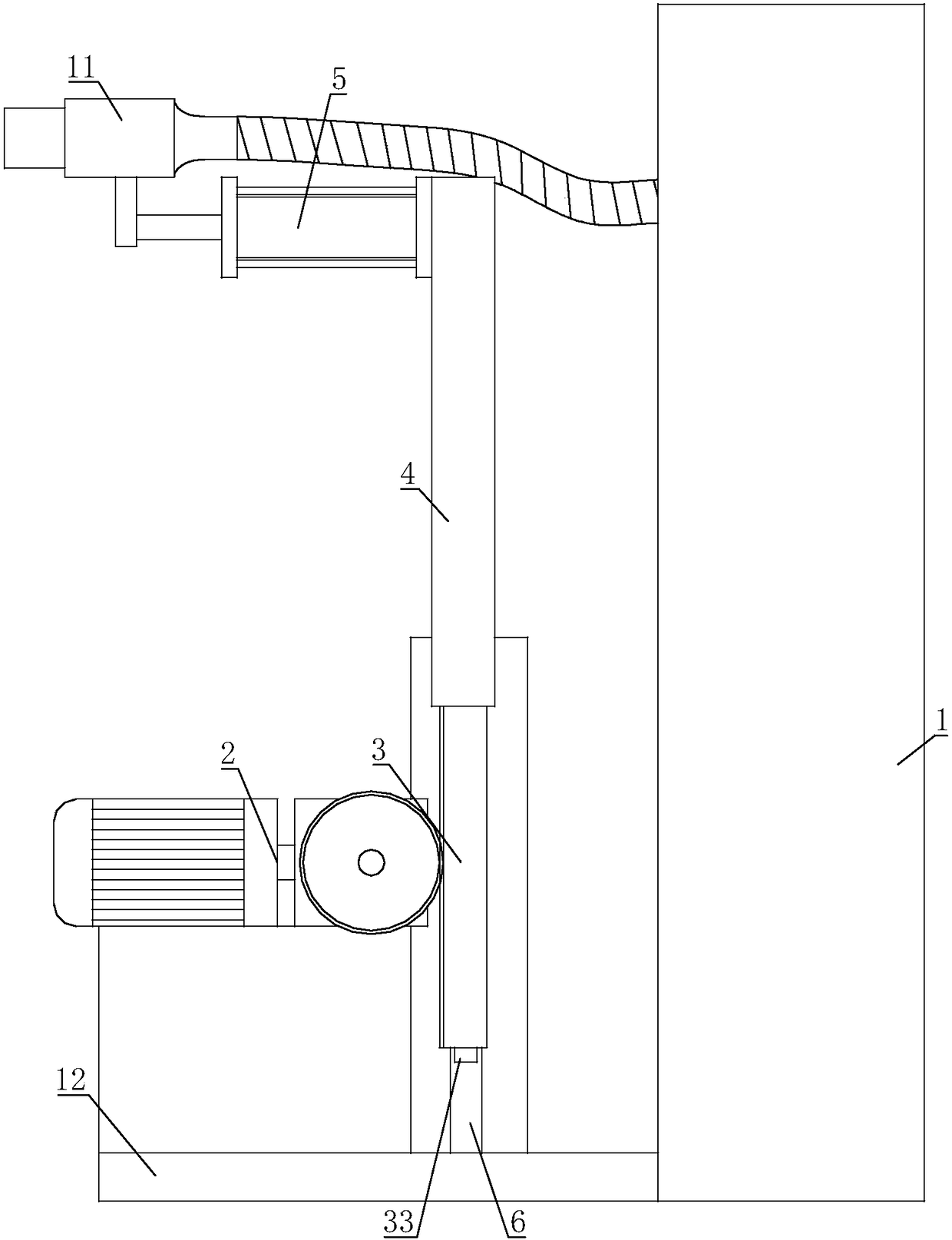
[0023] The electric shock-proof new energy vehicle charging pile includes a charging pile main body 1, and a charging plug 11 is connected to the charging pile main body 1; a mounting frame 12 is connected to the charging pile main body 1, and a driving mechanism 2 is installed on the mounting frame 12. The output end of the mechanism 2 is connected with a rack and pinion mechanism 3, and the other end of the rack and pinion mechanism 3 is connected with a lifting rod 4, and the other end of the lifting rod 4 is equipped with a cylinder 5, and the piston rod of the cylinder 5 is fixedly connected with the charging plug 11.

[0024] The drive mechanism 2 of the present invention can drive the rack-and-pinion mechanism 3 to move, and the rack-and-pinion mechanism 3 drives the lifting rod 4 to rise and fall, and the height of the charging plug 11 is adjusted accordingly to adapt to the height of the charging slots of different vehicles. When the cylinder 5 expands and contracts, t...

Embodiment 2

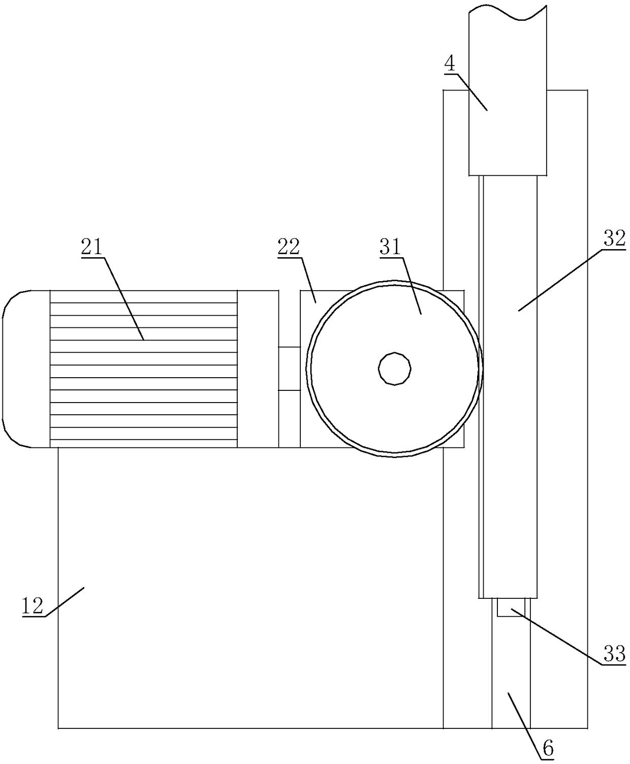
[0026] On the basis of Embodiment 1, the drive mechanism 2 includes a motor 21, the output shaft of the motor 21 is connected with a speed reducer 22, the motor 21 and the speed reducer 22 are all installed on the mounting frame 12, the output shaft of the speed reducer 22 and the gear The gear 31 of the rack mechanism 3 is connected.

[0027] After the motor 21 starts, the motor 21 drives the reducer 22 to act, and the reducer 22 drives the rack and pinion mechanism 3 to act, so that the elevating rod 4, the cylinder 5, and the charging plug 11 can be accurately lifted and lowered under the drive of the rack and pinion.

Embodiment 3

[0029] On the basis of Embodiment 1 or Embodiment 2, the rack and pinion mechanism 3 includes a gear 31, the gear 31 is connected to the output shaft of the drive mechanism 2, the gear 31 is meshed with a rack 32, and the elevating rod 4 is connected to the rack 32 on.

[0030] When the driving mechanism 2 drives the gear 31 to rotate, the rack 32 is driven up and down by the gear 31, so that the rack 32 can push the lifting rod 4 up and down, so that the charging plug 11 can be accurately inserted into the charging slot of the car.


PUM


Abstract

The invention relates to the field of new-energy vehicle charging piles, in particular to an electric shock resistant new-energy vehicle charging pile. According to the technical scheme, the electricshock resistant new-energy vehicle charging pile comprises a charging pile body, and a charging plug is connected to the charging pile body. The charging pile body is connected with an installation frame, and the installation frame is provided with a driving mechanism; the output end of the driving mechanism is connected with a gear rack mechanism, and the other end of the gear rack mechanism is connected with a lifting rod; and the other end of the lifting rod is connected with an air cylinder, and a piston rod of the air cylinder is fixedly connected with the charging plug. The electric shock resistant new-energy vehicle charging pile can be inserted and pulled automatically to avoid electric shock of a human body, and the problems that an existing new energy car need a hand-hold gun tocharge and the human body can be electrocuted are solved.

Description

technical field [0001] The invention relates to the field of new energy vehicle charging piles, in particular to an electric shock-proof new energy vehicle charging pile. Background technique [0002] The function of the charging pile is similar to the refueling machine in the gas station. It can be fixed on the ground or wall, and installed in public buildings (public buildings, shopping malls, public parking lots, etc.) and residential area parking lots or charging stations. Charge all models of electric vehicles. The input end of the charging pile is directly connected to the AC grid, and the output end is equipped with a charging plug for charging the electric vehicle. Charging piles generally provide two charging methods: conventional charging and fast charging. People can use a specific charging card to swipe the card on the human-computer interaction interface provided by the charging pile to perform corresponding charging methods, charging time, and cost data printi...

Claims


Application Information

Patent Timeline
Patent Type & Authority Applications(China)
IPC IPC(8): B60L11/18
CPCB60L53/16B60L53/30B60L53/31Y02T10/70Y02T10/7072Y02T90/12Y02T90/14
Inventor 曾皓
Owner 郑州恒之博新能源科技有限公司
Why Eureka
Try Eureka