Method for controlling converter tapping roughing slag through annular converter tapping hole gas blowing

A technology of gas blowing control and tapping hole, which is applied in the field of ring converter tapping hole gas blowing control converter tapping slag, which can solve the problems of difficult on-site operation, large space occupation, instability, etc., and improve the quality of molten steel and yield, improve the yield of molten steel, and the effect of simple device structure

Inactive Publication Date: 2018-07-10
NORTHEASTERN UNIV
View PDF4 Cites 6 Cited by
  • Summary
  • Abstract
  • Description
  • Claims
  • Application Information

AI Technical Summary

Problems solved by technology

This patent is aimed at the problem of slag blocking and tapping, and mainly has the following disadvantages: the equipment is complex and the installation and maintenance costs are high, the on-site operation is difficult and it occupies a large space, and it is not suitable for large-scale application of on-site mass production
This patent has the following deficiencies: the amount of gas generated by the slag blocking ball is uncontrollable, and it is difficult to stably control the slag under the vortex; it is mainly aimed at the slag entrainment of the vortex, and does not consider the slag caused by the drainage sinkhole, and does not propose to control the drainage sinkhole Measures against slag; according to manual experience, observe the surface of molten steel and then add slag blocking balls, which is unstable and reduces labor efficiency

Method used


Image

  • Method for controlling converter tapping roughing slag through annular converter tapping hole gas blowing
  • Method for controlling converter tapping roughing slag through annular converter tapping hole gas blowing
  • Method for controlling converter tapping roughing slag through annular converter tapping hole gas blowing

Examples


Embodiment 1

[0024] The converter used in this embodiment is 60 tons.

[0025] The method for controlling the slag in the tapping process of the ring converter by blowing air at the tap hole of the ring converter of the present invention is as follows:

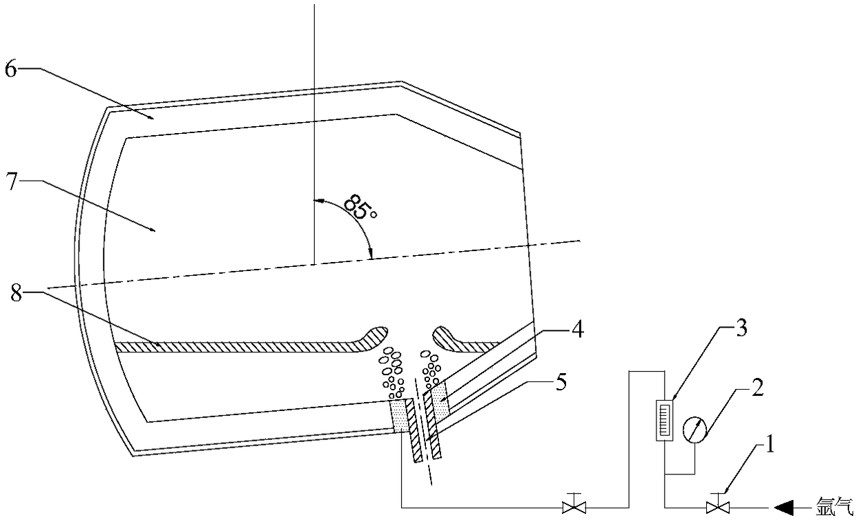
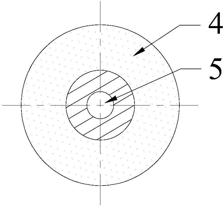
[0026] Step 1: Arrange ring-shaped breathable bricks 4 around the converter tapping hole 5, and the bottom of the ring-shaped breathable bricks 4 is connected to a blowing device; wherein, the gas fed into the blowing device is inert gas or nitrogen; the ring-shaped breathable bricks 4 are set on the converter tapping Around the mouth 5, the upper end surface of the annular air-permeable brick 4 is circular, the width of the annular air-permeable brick 4 is 100mm, and the height of the annular air-permeable brick 4 is the same as the width of the lining of the converter 6;

[0027] Step 2: At the end of the converter tapping process, when the tilting angle of the converter 6 is 85 degrees, the gas is introduced into the molten steel 7 in t...

Embodiment 2

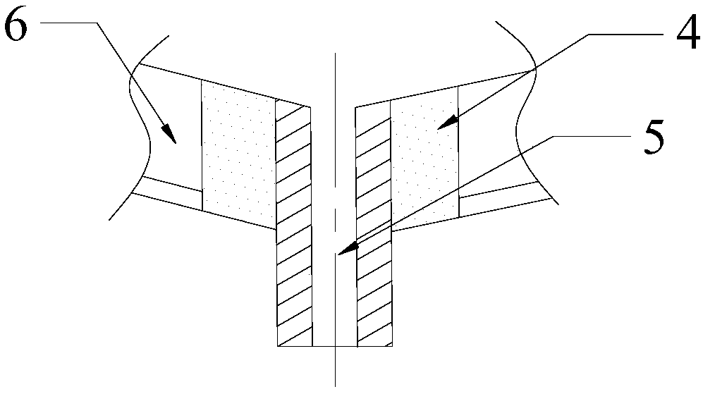
[0031] The converter used in this embodiment is 120 tons. The device process schematic diagram of this embodiment is as figure 2 As mentioned above, the A-A cross-sectional view of its tapping hole and annular breathable brick is shown in 3, and the top view of its tapping hole and annular breathable brick is shown in image 3 shown.

[0032] The method for controlling the slag in the tapping process of the ring converter by blowing air at the tap hole of the ring converter of the present invention is as follows:

[0033] Step 1: Arrange ring-shaped breathable bricks 4 around the converter tapping hole 5, and the bottom of the ring-shaped breathable bricks 4 is connected to a blowing device; wherein, the gas fed into the blowing device is inert gas or nitrogen; the ring-shaped breathable bricks 4 are set on the converter tapping Around the mouth 5, the upper end surface of the annular air brick 4 is circular, the width of the annular air brick 4 is 350mm, and the height of ...

Embodiment 3

[0038] The converter used in this embodiment is 180 tons.

[0039] The method for controlling the slag in the tapping process of the ring converter by blowing air at the tap hole of the ring converter of the present invention is as follows:

[0040] Step 1: Arrange ring-shaped breathable bricks 4 around the converter tapping hole 5, and the bottom of the ring-shaped breathable bricks 4 is connected to a blowing device; wherein, the gas fed into the blowing device is inert gas or nitrogen; the ring-shaped breathable bricks 4 are set on the converter tapping Around the mouth 5, the upper end surface of the annular air-permeable brick 4 is circular, the width of the annular air-permeable brick 4 is 600mm, and the height of the annular air-permeable brick 4 is the same as the width of the lining of the converter 6;

[0041] Step 2: At the end of the converter tapping, when the tilting angle of the converter 6 is 90 degrees, gas is introduced into the molten steel 7 in the converte...


PUM

PropertyMeasurementUnit
widthaaaaaaaaaa

Abstract

The invention relates to a method for controlling converter tapping roughing slag through annular converter tapping hole gas blowing, and belongs to the technical field of converter steel making. Themethod comprises the following steps of (1) installing annular ventilation bricks around a converter tapping hole; connecting a gas blowing device onto the bottom of the annular ventilation bricks, wherein gas blown in the gas blowing device is inert gas; (2) at the converter tapping tail period, when the converter inclination angle is 85 to 90 degrees, introducing gas into the converter through the annular ventilation bricks so that a steel liquid exposure and slag-layer-free round convex region is formed in the steel slag interface position above the converter tapping hole and is used for inhibiting the converter tapping roughing slag; (3) after the converter tapping stopping, stopping the gas introduction. The method has the advantages that the roughing slag due to current merging vortex and flow discharging sinking pits can be effectively inhibited; the molten steel quality and yield can be improved. The molten steel residue steel quantity in the converter tapping process can be effectively reduced; the molten steel yield is improved; the structure of the device is simple; the operation is convenient; the method is applicable to field mass production application.

Description

technical field [0001] The invention belongs to the technical field of converter steelmaking, and in particular relates to a method for controlling converter tapping slag by blowing air around a converter tapping hole. Background technique [0002] The slag during the tapping process of the converter will adversely affect the quality of molten steel. At the end of the converter tapping process, after most of the molten steel is discharged, the confluence vortex and drainage sinkhole above the converter tapping hole will cause converter tapping slag, which will seriously affect the quality of molten steel, reduce the yield of molten steel, and reduce the life of refractory materials. , increasing the processing time of the refining process. At present, it is generally operated by manual experience. In the later stage of converter tapping, observe the tapping situation, add slag blocking balls, slag blocking plugs, etc. to control the slag, but manual operation is dangerous a...

Claims


Application Information

Patent Timeline
Patent Type & Authority Applications(China)
IPC IPC(8): C21C5/28C21C5/46
CPCC21C5/28C21C5/4653
Inventor 郑淑国邹琦华金龙朱苗勇
Owner NORTHEASTERN UNIV
Why Eureka
Try Eureka