Leakproof device for air conditioner refrigerant

A refrigerant and anti-leakage technology, applied in air-conditioning systems, space heating and ventilation, household heating, etc., can solve problems such as waste, refrigerant loss, and environmental pollution, and achieve low cost, reasonable structure, and leakage prevention. Effect

Pending Publication Date: 2018-07-10
蚌埠市思洁节能科技有限公司
View PDF0 Cites 1 Cited by
  • Summary
  • Abstract
  • Description
  • Claims
  • Application Information

AI Technical Summary

Problems solved by technology

[0002] Air conditioners are one of the indispensable household appliances. Ordinary household air conditioners can be divided into internal units and external units. The internal units and external units are connected by pipelines. The interior of the air conditioner forms a refrigeration circuit for the circulation of refrigerant. Air conditioners are widely used in During the process, it is often necessary to dismantle or move. The existing air conditioner is only equipped with protection valves on the two interfaces of the external unit of the air conditioner, which can recover part of the refrigerant to the external unit, but it will inevitably cause the copper tube and the internal unit to be damaged. Refrigerant loss causes unnecessary waste and pollutes the environment
[0003] Moreover, when the existing air conditioner is moved, it needs to be operated by professionals, and the external machine is vacuumed and the refrigerant capacity is replenished. The process is cumbersome and increases the economic expenditure of the user.

Method used


Image

  • Leakproof device for air conditioner refrigerant
  • Leakproof device for air conditioner refrigerant
  • Leakproof device for air conditioner refrigerant

Examples


Embodiment Construction

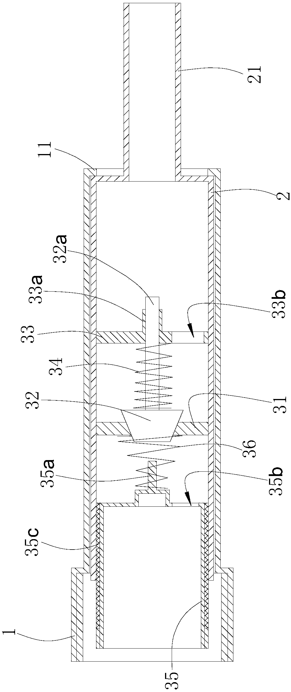
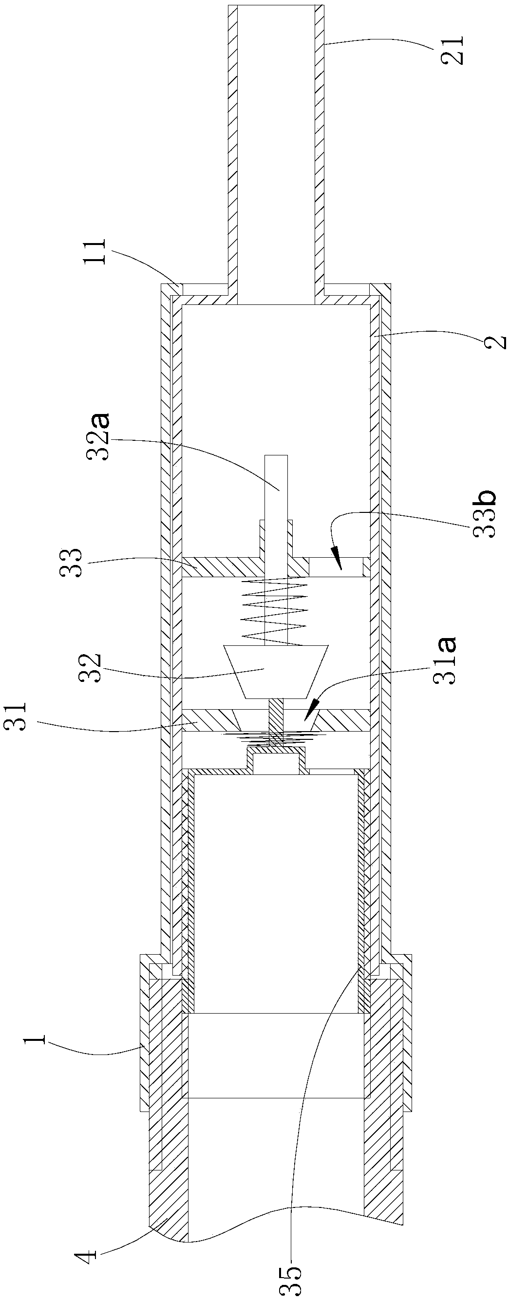
[0025] Such as Figures 1 to 4 shown

[0026] The anti-leakage device includes an outer connecting pipe 1, an inner connecting pipe 2 and a control valve assembly.

[0027] The outer diameter of the front part of the external connection pipe 1 is slightly larger than the outer diameter of the rear part of the external connection pipe 1. The inner wall of the front part of the external connection pipe 1 is provided with an internal thread that matches the interface 4 of the external unit of the air conditioner. Ring 11.

[0028] The inner connecting pipe 2 is sleeved in the outer connecting pipe 1, the outer diameter of the inner connecting pipe 2 is larger than the inner diameter of the inner convex ring 11, and the inner connecting pipe 2 extends to the rear side with an intubation tube 21, and the inner hole of the intubating pipe 21 communicates with the inner hole of the inner connecting pipe 2, The axis of the insertion tube 21 is collinear with the axial direction of t...


PUM


Abstract

The invention provides a leakproof device for air conditioner refrigerant. The leakproof device comprises an inner connection pipe and a control valve assembly. One side of the inner connection pipe is connected with an interface of an outdoor unit of an air conditioner, and the end of the other side of the inner connection pipe fixedly communicates with a copper tube of the air conditioner. The control valve assembly is arranged in the inner connection pipe and comprises a push pipe, a seal disc, a seal plate, a first spring and a support plate. The support plate is located at the interface position far away from the outdoor unit of the air conditioner relative to the seal plate. The seal plate is provided with a seal hole. The seal disc extends toward the support plate to form a guide rod. The end of the guide rod penetrates the support plate. The first spring is mounted on the guide rod in a sleeving manner. One end of the first spring abuts against the seal disc, and the other endof the first spring abuts against the support plate. The support plate is provided with a first through hole. A jacking rod extends out of the push pipe. By means of the leakproof device, circulationof cooling liquid is not hindered when the air conditioner is used normally; and the leakproof device can be closed automatically when the air conditioner needs to be dismounted and moved, so that thecooling liquid is prevented from leaking. The leakproof device has the beneficial effects of being reasonable in structure, low in cost, economical and environmentally friendly.

Description

technical field [0001] The invention relates to an anti-leakage device for air-conditioning refrigerant. Background technique [0002] Air conditioners are one of the indispensable household appliances. Ordinary household air conditioners can be divided into internal units and external units. The internal units and external units are connected by pipelines. The interior of the air conditioner forms a refrigeration circuit for the circulation of refrigerant. Air conditioners are widely used in During the process, it is often necessary to dismantle or move. The existing air conditioner is only equipped with protection valves on the two interfaces of the external unit of the air conditioner, which can recover part of the refrigerant to the external unit, but it will inevitably cause the copper tube and the internal unit to be damaged. The loss of refrigerant causes unnecessary waste and pollutes the environment. [0003] Moreover, when the existing air conditioner is moved, pr...

Claims


Application Information

Patent Timeline
IPC IPC(8): F24F1/34
CPCF24F1/34
Inventor 李家敏
Owner 蚌埠市思洁节能科技有限公司
Why Eureka
Try Eureka