Temperature-controllable fuel boiler

A water boiler and fuel technology, which is applied in water heaters, lighting and heating equipment, fluid heaters, etc., can solve the problems of inability to detect scale formation in the water tank, heat loss, cracking of the straight fire pipe water tank, etc., to improve self-sustainability. capacity and heating efficiency, the effect of reducing thermal stress, reducing fuel consumption

Pending Publication Date: 2018-07-10
SANHE KEDA IND +1
View PDF0 Cites 1 Cited by
  • Summary
  • Abstract
  • Description
  • Claims
  • Application Information

AI Technical Summary

Problems solved by technology

This kind of oil-fired boiling water boiler has a large volume and has the following disadvantages: 1) Since the direct fire pipes are mostly vertically arranged, the water in the water tank directly exchanges heat and cold during the heating process, and the chimney exhausts the direct fire pipes The function makes the direct fire pipe directly exchange heat and cold between the upper and lower water during the heating process. In addition, the chimney exhausts the direct fire pipe. The water boiled for a long time before the water below reached the boiling temperature, and the fuel consumption was too much; 2) Since the straight fire pipe is arranged vertically, the high-temperature flue gas generated by the burner will be directly discharged from the chimney, which not only causes heat loss loss, and the high flue gas temperature can lead to cracking of the direct fire pipe and the water tank; 3) Since the water in the water tank is in a boiling state after being boiled, if you want to drink warm water, you can only mix it with cold or hot water Obtained in a natural and cool way, which affects people's drinking needs; 4) It is impossible to detect the formation of scale in the water tank, which affects the heating efficiency

Method used


Image

  • Temperature-controllable fuel boiler
  • Temperature-controllable fuel boiler
  • Temperature-controllable fuel boiler

Examples


Embodiment Construction

[0021] The present invention will be further described in detail below with reference to the drawings and specific embodiments.

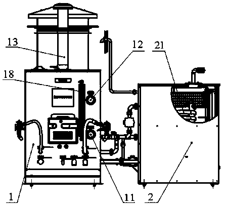
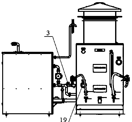
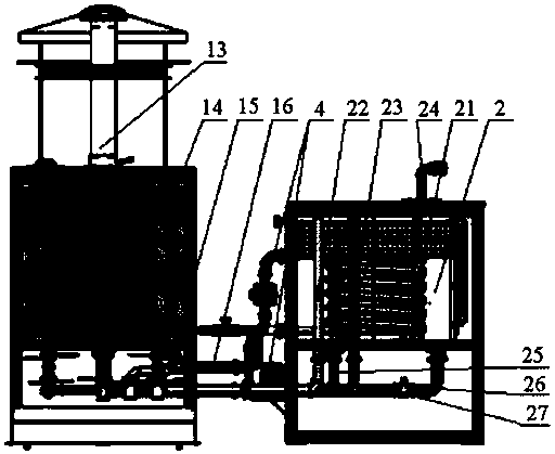
[0022] A temperature-controllable oil-fired water boiler is a normal pressure, energy-saving stainless steel water boiler, which includes a water boiler 1 and a water make-up tank 2 connected by pipelines. The working state of the water boiler and the water make-up tank is controlled by a PLC controller.

[0023] The boiling water furnace is an internal combustion, horizontal, two-pass diesel furnace. The heat insulation material of the furnace body is polyurethane and the fuel is diesel. The boiling water furnace has a size of 1600mm×800mm×1200mm and a capacity of 300L. The boiling water furnace includes a furnace body, a water storage tank 112 is arranged in the furnace body, a burner 14 is arranged under the water storage tank, and the water storage tank and the burner in the furnace body are placed in the furnace 113; the top of the furnace body is pr...


PUM


Abstract

The invention discloses a temperature-controllable fuel boiler. The temperature-controllable fuel boiler comprises a boiler body and a PLC controller controlling a working state of the boiler body, wherein a hearth for storing a burner and a water storage box for storing water are arranged in the boiler body, and the top of the boiler body is provided with a smoke tube communicated with the hearth; the bottom side wall of the boiler body is provided with a hot water faucet communicated with a hot water outlet of the water storage box by virtue of a hot water outlet pipe; and a water supplementing box is also arranged by the side of the boiler body, a coil pipe for cooling the boiled water delivered by the boiler body is arranged in the water supplementing box, a water inlet of the coil pipe is communicated with a hot water outlet of the water storage box by virtue of a hot water pipeline, the water outlet of the coil pipe is communicated to a warm water faucet on the bottom side wall of the boiler body by virtue of a warm water pipe, and the warm water pipe is provided with a water pump and an electromagnetic valve connected with the output end of the PLC controller. The controllable temperature fuel boiler integrally controls the ignition, burning and monitoring, realizes the accurate temperature control, can improve the heating efficiency and self-sustaining capability, and can reduce the energy consumption.

Description

Technical field [0001] The invention relates to the technical field of boiling water furnaces, in particular to an oil-fired boiling water furnace. Background technique [0002] Boiling water boilers are water heating equipment designed and developed to meet the drinking water needs of all kinds of people. Common water boilers include electric water boilers, oil-fired water boilers, gas-fired water boilers, and coal-fired water boilers. Oil-fired water boilers use oil to obtain heat. Equipment to heat water. [0003] Traditional oil-fired boiling water boilers usually adopt a vertical oil-fired boiler structure. This boiler is composed of a burner, a furnace and a water tank. The water tank is vertically equipped with a direct fire tube. The lower part of the direct fire tube is connected to the furnace, and the upper part is connected to the chimney. The water tank outside the tube is filled with water, the heat generated by the burner is discharged from the chimney through the s...

Claims


Application Information

Patent Timeline
Patent Type & Authority Applications(China)
IPC IPC(8): F24H1/36F24H9/00F24H9/18F24H9/20
CPCF24H1/36F24H9/0005F24H9/1836F24H9/2035
Inventor 朱文娴赵英甄景荣
Owner SANHE KEDA IND
Why Eureka
Try Eureka