Micro-channel structure auxiliary driven loop heat pipe

An auxiliary drive, loop heat pipe technology, applied in indirect heat exchangers, lighting and heating equipment, etc., can solve the problem of unreliable start of loop heat pipes, and achieve the effect of good starting and running performance, high flexibility, and ensuring reliability.

Pending Publication Date: 2018-07-10
TECHNICAL INST OF PHYSICS & CHEMISTRY - CHINESE ACAD OF SCI
View PDF6 Cites 6 Cited by
  • Summary
  • Abstract
  • Description
  • Claims
  • Application Information

AI Technical Summary

Problems solved by technology

[0006] The purpose of the present invention is to provide a loop heat pipe driven by a micro-channel structure, which is inte

Method used


Image

  • Micro-channel structure auxiliary driven loop heat pipe
  • Micro-channel structure auxiliary driven loop heat pipe
  • Micro-channel structure auxiliary driven loop heat pipe

Examples


Embodiment Construction

[0026] The technical solutions in the embodiments of the present invention will be clearly and completely described below in conjunction with the accompanying drawings in the embodiments of the present invention. Obviously, the described embodiments are only a part of the embodiments of the present invention, rather than all the embodiments. Based on the embodiments of the present invention, all other embodiments obtained by those of ordinary skill in the art without creative work shall fall within the protection scope of the present invention.

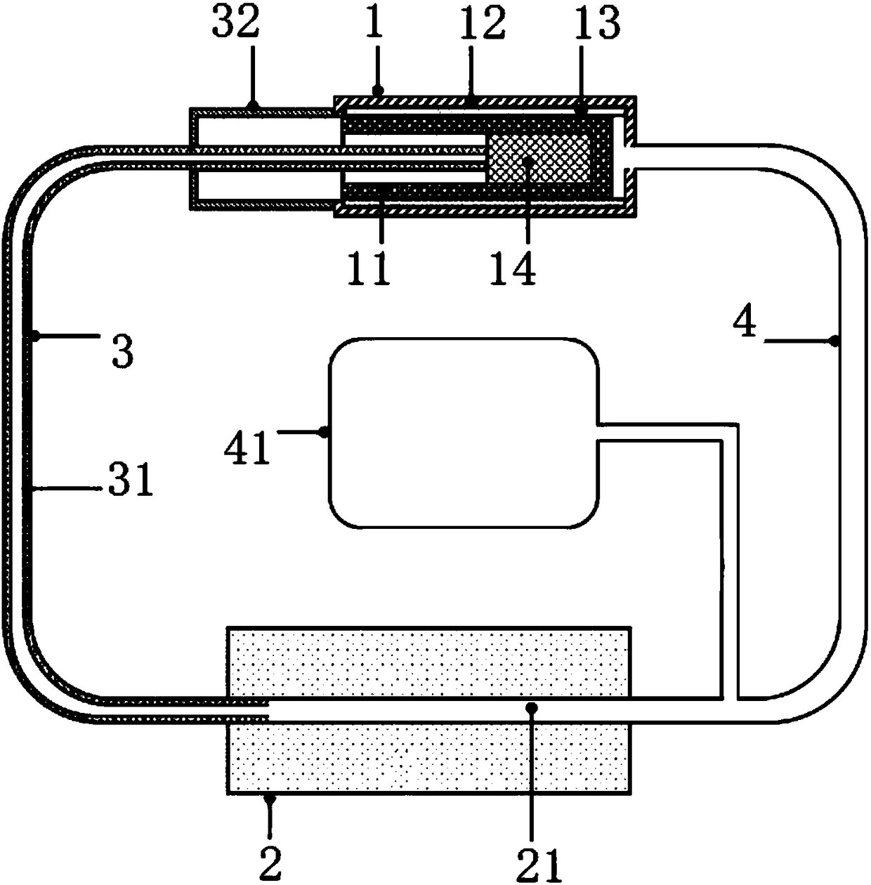
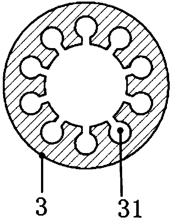
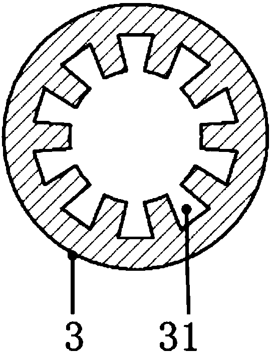
[0027] See Figure 1-Figure 4 The embodiment of the present invention provides a loop heat pipe driven by a micro-channel structure, including an evaporator 1 and a condenser 2. The liquid outlet of the condenser 2 is connected to the liquid inlet of the evaporator 1 through a liquid pipeline 3, and The gas outlet of the evaporator 1 is connected to the inlet of the condenser 2 through the gas pipeline 4, that is, the condenser 2, the li...


PUM


Abstract

The invention relates to heat control equipment, and provides a micro-channel structure auxiliary driven loop heat pipe. The micro-channel structure auxiliary driven loop heat pipe comprises an evaporator and a condenser. A liquid outlet of the condenser communicates with a liquid inlet of the evaporator through a liquid pipeline, a gas outlet of the evaporator communicates with a gas inlet of thecondenser through a gas pipeline, multiple micro-channels are formed in the inner wall of the liquid pipeline and sequentially distributed in the circumferential direction of the liquid pipeline at intervals, and stretch in the length direction of the liquid pipeline, a liquid absorption core is arranged in the evaporator, one end of each micro-channel stretches into the condenser, and the otherend of each micro-channel is connected with the liquid absorption core. The micro-channels are formed in the inner wall of the liquid pipeline, a liquid-state working medium can be conveyed with the help of the capillary effect of the micro-channels, supply of the liquid-state working medium can be continuously provided for the evaporator without gravity assisting and additional power consumption,and the starting reliability and the anti-gravity working stability of the loop heat pipe are guaranteed.

Description

Technical field [0001] The invention relates to thermal control equipment, in particular to a loop heat pipe driven by a micro-channel structure. Background technique [0002] The heat pipe is an efficient heat transfer device, its heat transfer capacity is one or two orders of magnitude higher than the heat conduction of metal, and is called a thermal superconductor. In traditional heat pipes, the capillary structure is usually composed of a channel or a sintered porous structure, and is distributed along the length of the heat pipe. Although the structure is simple, the flexibility is poor. In addition, the capillary structure is covered in the axial direction of the heat pipe, and the liquid flow resistance is large , Liquid and gas flow in opposite directions in the same space, and there is a problem of carrying, which affects the heat transfer capacity of the heat pipe to further improve. [0003] The loop heat pipe is an improved and optimized high-efficiency heat transfer d...

Claims


Application Information

Patent Timeline
IPC IPC(8): F28D15/04
CPCF28D15/043
Inventor 赵雅楠梁惊涛陈厚磊
Owner TECHNICAL INST OF PHYSICS & CHEMISTRY - CHINESE ACAD OF SCI
Why Eureka
Try Eureka