Supercharge Your Innovation With Domain-Expert AI Agents!

Intelligent mopping machine working state identification control mechanism and identification detection method

A technology of working state and control mechanism, applied in cleaning action control, robot cleaning machine, manual floor scrubbing machinery, etc., can solve the problems of personnel or ground, floor scrubbing machine damage, time-consuming and laborious, poor safety and reliability, etc. Simple, safe and reliable, the effect of prolonging the service life

Active Publication Date: 2020-07-28
NINGBO SAWADIKA ELECTRICAL APPLIANCE
View PDF6 Cites 0 Cited by
  • Summary
  • Abstract
  • Description
  • Claims
  • Application Information

AI Technical Summary

Problems solved by technology

[0003] The present invention mainly provides a simple structure, safety and reliability, which can automatically detect and identify the state of the mopping machine, and control the mopping machine to perform related actions according to the detected state. It solves the technical problems existing in the prior art that it is necessary to turn off the power switch under working conditions such as changing the mop, which is not only time-consuming and laborious, but also easily causes damage to personnel, the ground, and the mopping machine in the case of misoperation, and poor safety and reliability.

Method used


Image

  • Intelligent mopping machine working state identification control mechanism and identification detection method
  • Intelligent mopping machine working state identification control mechanism and identification detection method
  • Intelligent mopping machine working state identification control mechanism and identification detection method

Examples


Embodiment

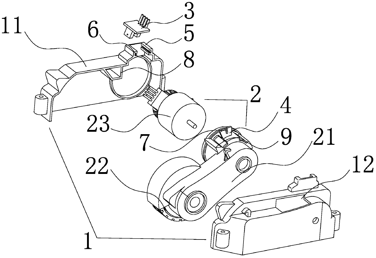
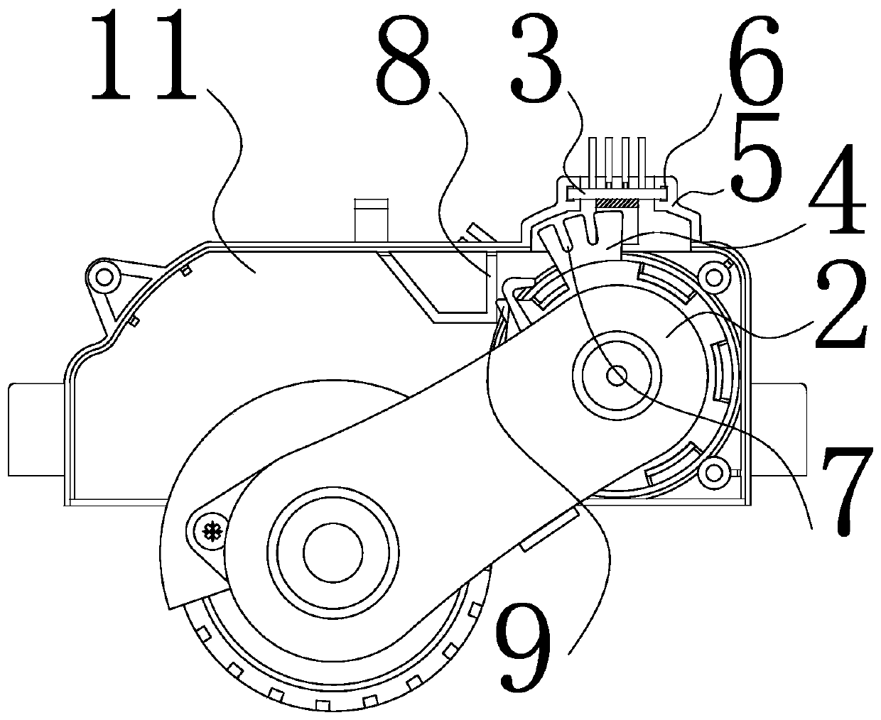
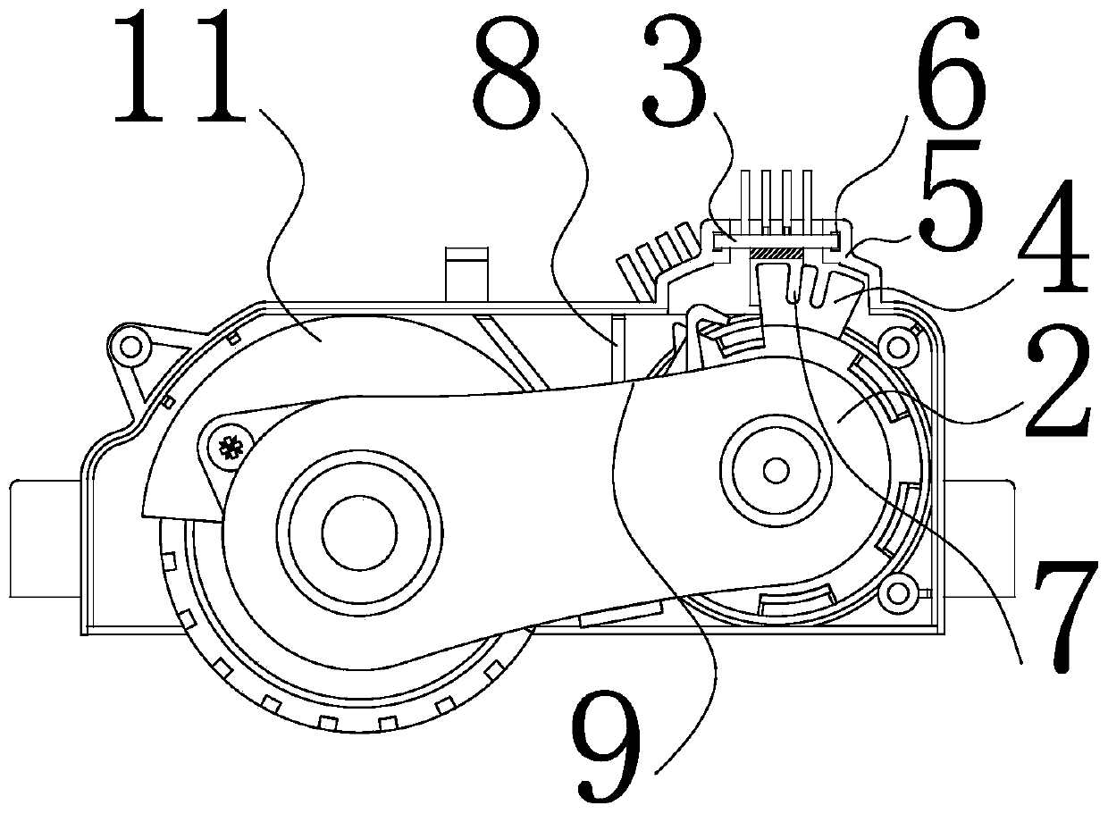
[0024] Such as figure 1 As shown, a kind of intelligent ground mopping machine working state recognition control mechanism of the present invention comprises the wheel set case 1 formed by the docking of the left cover 11 and the right cover 12, and the wheel set cover is housed in the wheel set cover 1. The power assembly 2, the wheel set power assembly 2 includes a U-shaped wheel frame 21, the open end of the U-shaped wheel frame 21 faces outward horizontally, and is coaxial on the corresponding U-shaped wheel frame 21 open end outside the wheel set cover 1. Roller wheels 22 are installed, and a drive motor 23 is coaxially installed on the opening end of the corresponding U-shaped wheel frame 21 in the wheel set cover 1, and the two ends of the output shaft of the drive motor 23 are respectively connected to the left cover 11 and the right cover 12 in rotation. Above, the corresponding wheel cover 1 above the wheel set power assembly 2 extends downwards integrally to form a ...


PUM


Abstract

The invention discloses a floor mopping machine structure, and provides an intelligent floor mopping machine working state recognizing and control mechanism which is simple in structure, safe and reliable, can automatically detect and recognize the state of a floor mopping machine and can execute related actions according to the detected state, and a recognizing and detecting method. The technicalproblems that a switch needs to be switched off under the working conditions of mop replacing and the like, time and labor are wasted and the harms to personnel or the damage to the ground and a floor mopping machine is quite easily caused under the condition of misoperation in the prior art are solved. The recognizing and control mechanism comprises a wheel set case and a wheel set power assembly covered with the wheel set case. One end of the wheel set power assembly is rotationally connected to the wheel set case, and the other end of the wheel set power assembly extends out of the wheel set case and supported on the ground through wheels. An optical coupling groove is formed in the wheel set case. An optical grating piece is arranged on the wheel set power assembly and extends in a U-shaped opening of the optical coupling groove. The optical coupling groove is connected to a control system. The control system controls the working state of the intelligent floor mopping machine according to a detection signal sent by the optical coupling groove to the optical grating piece.

Description

technical field [0001] The present invention relates to a floor mopping machine structure, in particular to an intelligent floor mopping machine working state recognition control which is simple in structure, safe and reliable, can automatically detect and identify the state of the floor mopping machine, and controls the floor mopping machine to perform related actions according to the detected state Mechanism and identification detection method. Background technique [0002] The traditional way of cleaning the ground is to use a mop. The process is completely dependent on manpower, and the labor intensity is high. In order to save physical strength and reduce people's labor, people have developed various intelligent automatic mopping machines, usually through the main machine. The motor drives the two mop cloths at the bottom to reciprocate and horizontally move to wipe the ground. When changing the mop cloth, it is often necessary to turn off the power switch of the intell...

Claims


Application Information

Patent Timeline
Patent Type & Authority Patents(China)
IPC IPC(8): A47L11/28A47L11/40G01D11/00
CPCA47L11/28A47L11/40A47L11/4011A47L11/4088A47L2201/00A47L2201/06G01D11/00
Inventor 陈锵锵
Owner NINGBO SAWADIKA ELECTRICAL APPLIANCE
Features
  • R&D
  • Intellectual Property
  • Life Sciences
  • Materials
  • Tech Scout
  • Unparalleled Data Quality
  • Higher Quality Content
  • 60% Fewer Hallucinations
Learn More