
Steel tube drilling device

A drilling device and a technology for steel pipes, applied in the field of steel pipes, can solve the problems such as the inability of the steel pipe drilling machine to dissipate heat and clamp the effect, instability, etc., and achieve the effects of improving stability and avoiding service life.

Inactive Publication Date: 2018-07-13
安徽雄风防护设施有限公司
View PDF10 Cites 13 Cited by
  • Summary
  • Abstract
  • Description
  • Claims
  • Application Information

AI Technical Summary

Problems solved by technology

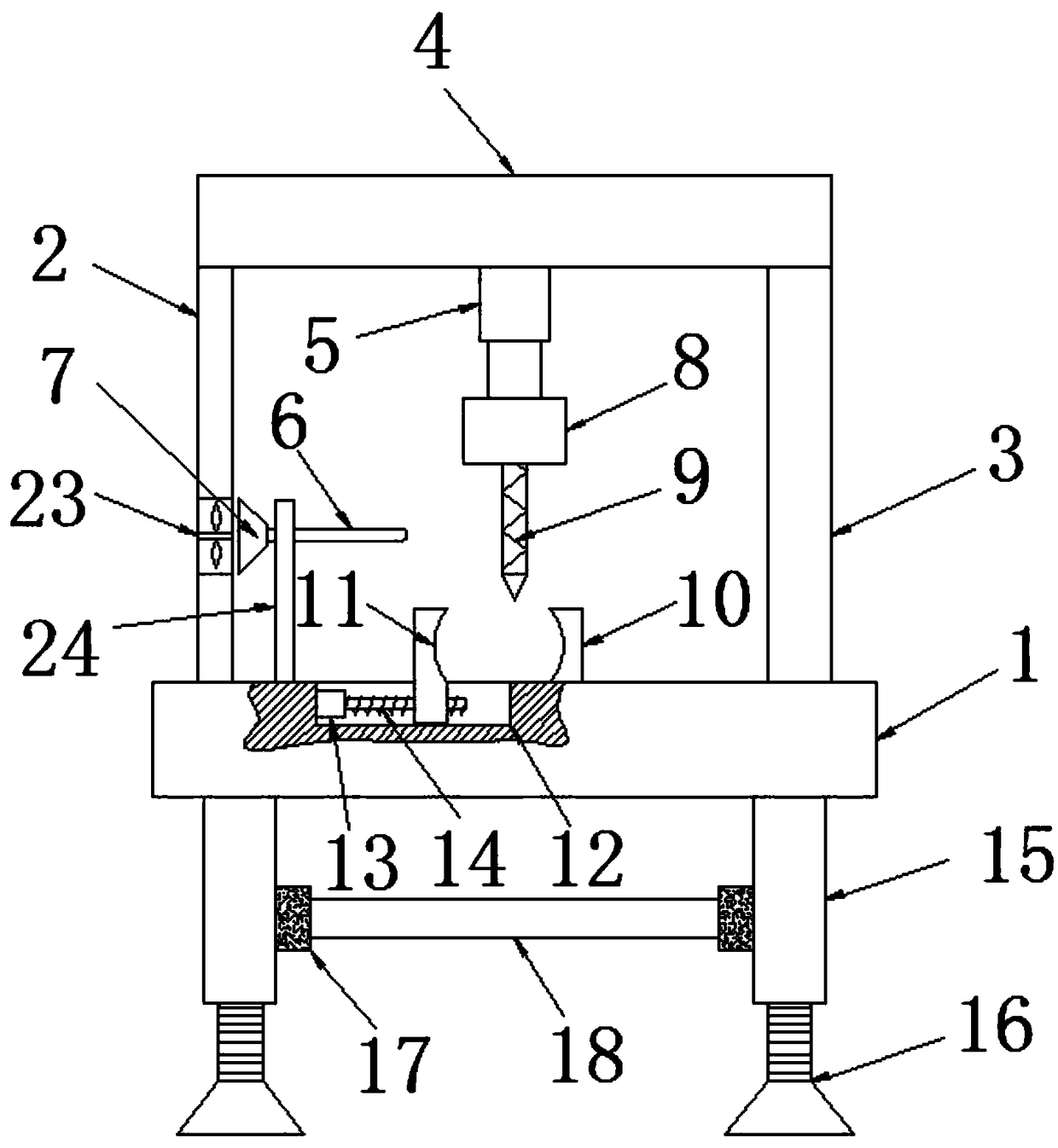
[0004] The purpose of the present invention is to solve the problem that the existing steel pipe drilling machine cannot dissipate heat and the clamping effect is unstable, and proposes a steel pipe drilling device

Method used


Image

  • Steel tube drilling device
  • Steel tube drilling device

Examples


Embodiment Construction

[0018] The following will clearly and completely describe the technical solutions in the embodiments of the present invention with reference to the accompanying drawings in the embodiments of the present invention. Obviously, the described embodiments are only some, not all, embodiments of the present invention.

[0019] In describing the present invention, it should be understood that the terms "upper", "lower", "front", "rear", "left", "right", "top", "bottom", "inner", " The orientation or positional relationship indicated by "outside", etc. is based on the orientation or positional relationship shown in the drawings, and is only for the convenience of describing the present invention and simplifying the description, rather than indicating or implying that the referred device or element must have a specific orientation, so as to Specific orientation configurations and operations, therefore, are not to be construed as limitations on the invention.

[0020] refer to Figure ...


PUM


Abstract

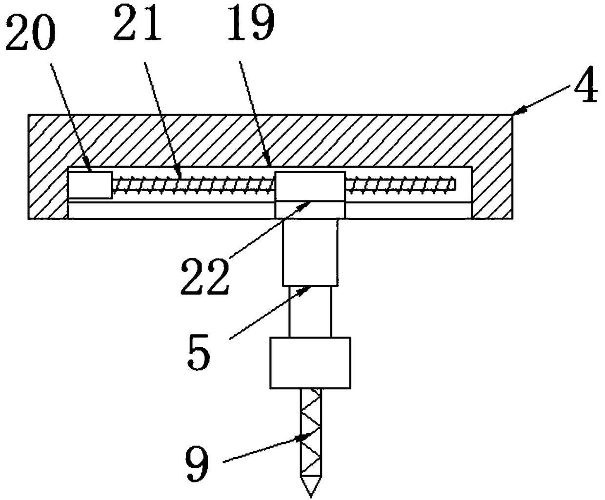
The invention discloses a steel tube drilling device. The steel tube drilling device comprises a base as well as a first supporting plate and a second supporting plate which are arranged at left and right sides of the upper end of the base, wherein the upper end of the first supporting plate and the upper end of the second supporting plate are connected with the same transverse plate; a T-shaped slide slot is longitudinally formed in the lower end of the transverse plate; the T-shaped slide slot is in sliding connection with a T-shaped slide block; the left side wall of the T-shaped slide slotis fixedly equipped with a first motor; the output end of the first motor is fixedly equipped with a first screw which is in threaded connection with the T-shaped slide block through a shaft coupler;the lower end of the T-shaped slide block is fixedly equipped with an air cylinder; the lower end of the air cylinder is fixedly equipped with a second motor; the output end of the second motor is fixedly equipped with a drill bit through a shaft coupler; the upper end of the base is fixedly equipped with a first clamping plate; a slide slot is horizontally formed in the upper end of the base; and the slide slot is in sliding connection with a second clamping plate. The steel tube drilling device is convenient to operate, can improve steel tube clamping stability and can dissipate heat for the drill bit; and the service life of the steel tube drilling device is prevented from being affected as a result of a too high drill bit temperature.

Description

technical field [0001] The invention relates to the technical field of steel pipes, in particular to a steel pipe drilling device. Background technique [0002] Drilling machine is a general term for machinery and equipment that uses a tool that is harder and sharper than the target to leave a cylindrical hole or hole on the target by means of rotary cutting or rotary extrusion. Also known as drilling rigs, punching machines, drilling machines, through-hole machines, etc. The desired effect is achieved by drilling precision parts. [0003] The existing drilling machine will generate temperature when drilling, and when the temperature is too high, it will affect the service life of the drill bit, and the existing drilling machine clamping is not high enough in stability. Therefore, the present invention has designed a kind of steel pipe drilling device. Contents of the invention [0004] The object of the present invention is to solve the problem that the existing steel ...

Claims


Application Information

Patent Timeline
IPC IPC(8): B23B41/00B23Q3/06B23Q11/10B23Q1/26
CPCB23B41/00B23Q1/26B23Q3/064B23Q11/10
Inventor 查何南熊集泉毕达熊根兰
Owner 安徽雄风防护设施有限公司
Learn More