
Contour detection method and contour detection device for aero-engine assembly

An aero-engine and detection method technology, which is applied in the direction of mechanical measuring devices, measuring devices, and mechanical devices, etc., can solve the problems of parts and pipelines exceeding the cross-sectional range, unable to guarantee the parallel movement of the sample, and high labor intensity, so as to achieve true detection results Reliable, the measurement results are true and reliable, and the effect of eliminating human factors

Inactive Publication Date: 2018-07-13
CHINA HANGFA GUIZHOU LIYANG AVIATION POWER CO LTD
View PDF5 Cites 1 Cited by
  • Summary
  • Abstract
  • Description
  • Claims
  • Application Information

AI Technical Summary

Problems solved by technology

The existing problems and shortcomings of this detection method are as follows: 1. There is no detection reference for the contour template, and the artificial control along the direction of the engine axis cannot ensure that the template moves parallel to the engine axis. The measurement process (action) is not stable, and the labor intensity is large. Untrue, resulting in artificial measurement errors; 2. During final assembly, limited by the fulcrum of the assembly vehicle, it can only detect the outline of the engine axis length from 0 to 888.5mm, which cannot meet the detection requirements of the largest solid outline in any direction on the length of 375mm to 2830mm ;3. When correcting engine accessory equipment and pipelines, there is no fixed center reference, causing components and pipelines to exceed the specified cross-sectional range

Method used


Image

  • Contour detection method and contour detection device for aero-engine assembly
  • Contour detection method and contour detection device for aero-engine assembly

Examples


Embodiment Construction

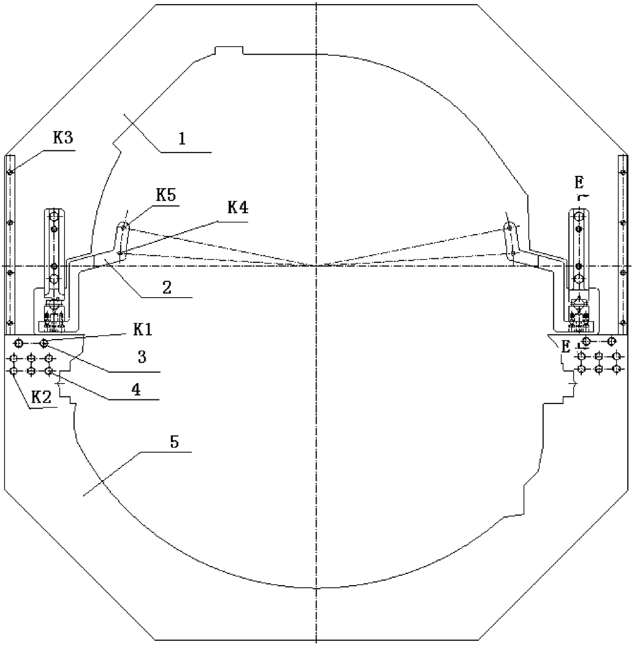
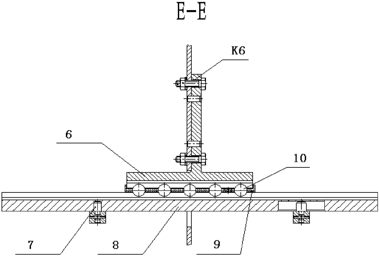
[0025] Such as figure 1 As shown, the detection device mainly consists of an upper profile template 1, a positioning bracket 2, a positioning pin 3, a bolt 4, a lower profile template 5, a slider (installed on the upper profile template) 6, and a positioning column (installed on the positioning bracket) 7 , guide rail 8, cage 9 and ball 10. The first section outline template is a whole, and the positioning pin 3 and the bolt 4 are not designed, and the use and operation steps are described below with the second section (second section). Step 1: Install the positioning bracket. Precise bolt hole positioning on the installation side of the external ducted rear receiver, the upper part of the external ducted front receiver, and the lower half of the external ducted front receiver, and a total of 4 positioning brackets with 2 fulcrums before and after installation to ensure 4 positioning The connecting line of the positioning column (front and back) on the bracket is parallel to...


PUM


Abstract

The invention provides a contour detection device for an engine. According to the invention, firstly, a detection device special for detecting the contour of the engine is designed. The detection device is mainly composed of an upper contour sample plate, a positioning support, a positioning plug pin, a bolt, a lower contour sample plate, a sliding block (installed on the upper contour sample plate) , a positioning column (installed on the positioning support), a guide rail, retainers and a ball. After that, the measurement is carried out. The method comprises the steps of 1, installing the positioning support; 2, installing the guide rail; 3, installing the retainers on the well installed guide rail, and ensuring the sliding to be flexible without the phenomenon of stagnation; 4, installing the upper contour sample plate and the lower contour sample plate, accurately installing the upper contour sample on the left and right retainers through the sliding block, uniformly applying the force left and right, and ensuring the smooth movement of the upper contour sample plate along the guide rail; 5, stably moving the contour sample plates. In this way, whether the contour of the engineis controlled within an allowable maximum contour range or not can be detected.

Description

technical field [0001] The invention belongs to the detection technology of the outline of the general assembly of the aero-engine, and relates to the detection of the overall shape of the engine, which ensures that the engine and the aircraft can pass through the assembly channel smoothly when assembling. Background technique [0002] After the final assembly of a certain type of engine is completed, it is necessary to detect the maximum outline of the engine axis in any direction in different cross-sections to ensure that the engine and aircraft can pass through the assembly channel smoothly during assembly. According to the requirements, the detection range of the maximum profile of the engine: starting from the intake end, the detection is carried out in all directions at 360° along the 375-2830mm length section of the engine axis. The existing profile template is held by two people, and the fit between the engine profile and the profile template is artificially compared...

Claims


Application Information

Patent Timeline
Patent Type & Authority Applications(China)
IPC IPC(8): G01B5/20
CPCG01B5/003G01B5/20
Inventor 陈燕青李平
Owner CHINA HANGFA GUIZHOU LIYANG AVIATION POWER CO LTD
Learn More