Optical splitter

A technology of optical splitters and splitters, applied in the direction of light guides, optics, instruments, etc., can solve the problem of affecting the use effect and market expansion prospects, the capacity of fiber distribution cannot meet user requirements, and the inconvenience of expanding the network of optical splitters and other problems, to achieve the effect of convenient and quick adjustment of optical communication lines, convenient and flexible installation, and convenient plug-in and pull-out

Pending Publication Date: 2018-07-13
HYC CO LTD
View PDF0 Cites 2 Cited by
  • Summary
  • Abstract
  • Description
  • Claims
  • Application Information

AI Technical Summary

Problems solved by technology

[0005] It can be seen that it is inconvenient to use the existing optical splitter to expand the network, and the fiber distribution capacity cannot meet the user's requirements, which affects the use effect and market expansion prospects; and it is inconvenient to plug and unplug, and the operation is complicated and time-consuming when adjusting the line. Sometimes it may also be necessary to disrupt other communication networks

Method used


Image

  • Optical splitter
  • Optical splitter
  • Optical splitter

Examples


Embodiment 1

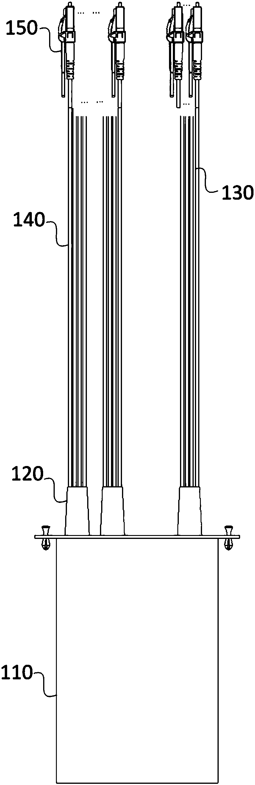
[0030] figure 1 It is a schematic structural diagram of the optical splitter in Embodiment 1 of the present invention, and this embodiment can be used in the case of splitting optical signals. Such as figure 1 As shown, the optical splitter includes: a module box 110 , a PLC splitter, a ferrule set 120 , an input optical fiber 130 , an output optical fiber 140 and an optical fiber connector 150 . Wherein, the PLC splitter is not shown in the figure.

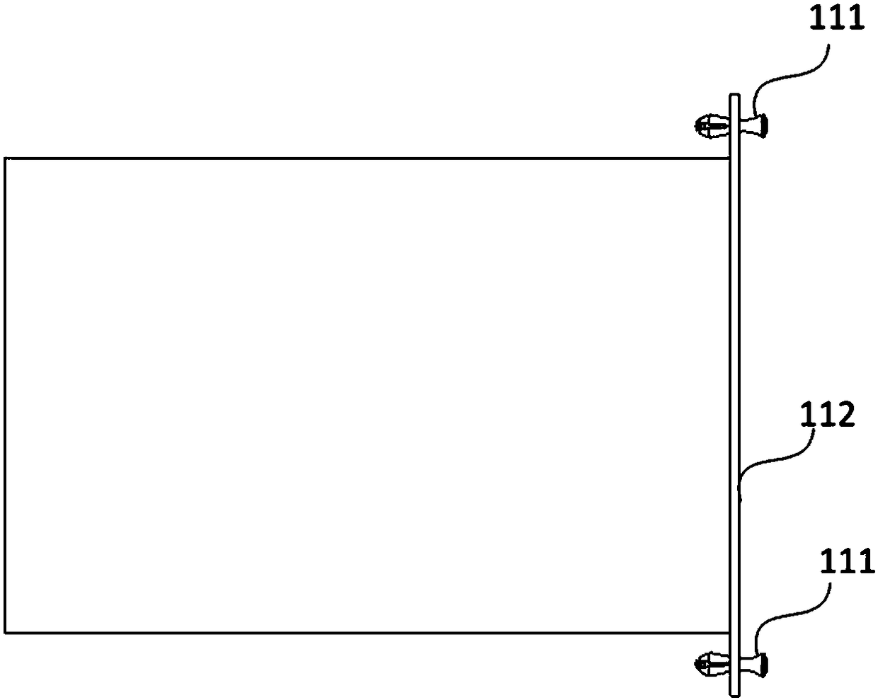
[0031] Specifically, the module box 110 includes at least one input panel hole and at least one output panel hole, and a bushing group 120 is respectively arranged in each said panel hole, and each group of bushings 120 includes at least one bushing; PLC branch The device is fixed inside the module box; the other end of the input optical fiber 130 at the input end of the PLC splitter extends to the outside of the module box 110 through the sleeve 120 arranged in the hole of the input panel, and is provided with an optical fiber...

Embodiment 2

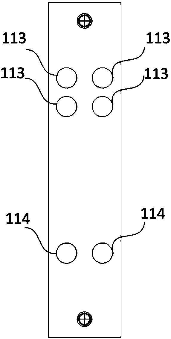
[0039] image 3 It is a schematic diagram of the connection mode of the optical fiber in the module box in the second embodiment of the present invention. This embodiment is based on the above-mentioned embodiment, and embodies the connection mode of the optical fiber in the module box.

[0040] Such as image 3 As shown, the PLC splitter 160 is fixed inside the module box 110, and the input end is on the side close to the panel hole 114, and the output end is on the side away from the panel hole 114. The input optical fiber 130 at the input end of the PLC splitter 160 extends to the outside of the module box 110 through the sleeve tube fixed in the input panel hole 114; the output optical fiber 140 at the output end of the PLC splitter 160 extends through the sleeve tube fixed in the output panel hole 113 to the outside of the module box 110. Wherein the casing is not shown in the figure.

[0041] Specifically, the PLC splitter is packaged into the LGX module box, and when...


PUM


Abstract

An embodiment of the invention discloses an optical splitter, comprising a module box, a PLC (programmable logic controller) splitter, sleeves, an input fiber and an output fiber; the module box includes at least one input panel hole and at least one output panel hole; at least one sleeve unit is arranged in each panel hole; the PLC splitter is fixed in the module box; the input fiber at the inputend of the PLC splitter is extended out of the module box through the sleeves in the input panel holes and is provided with a fiber connector; the output fiber at the output end of the PLC splitter is extended out of the module box through the sleeves arranged in the output panel holes and is provided with a fiber connector. The optical splitter has small size, good performance safety and reliability, good convenience and flexibility of mounting, and good convenience of capacity expansion; connection loss is reduced, the cost is reduced, networking capacity expansion of lines within a certainspatial range is achieved, and the fiber connectors are convenient to pull and plug during adjustment.

Description

technical field [0001] Embodiments of the present invention relate to the field of optical fiber communication, and in particular to an optical splitter. Background technique [0002] Optical splitter, also known as optical splitter, is one of the important passive components in optical fiber link. Optical splitters can be divided into two types: fusion tapered type and planar waveguide type (PLC type) according to the principle of light splitting. PLC optical splitter is an integrated waveguide optical power sharing device based on quartz version. It is one of the most important passive devices in optical fiber link. connected devices. [0003] PLC optical splitters are packaged into different structures according to different usage methods and locations, so that they can be used conveniently. Among them, the computer room mostly uses rack-mounted or distribution frames and other installation structures. Box-type optical splitters are widely used and packaged in racks or...

Claims


Application Information

Patent Timeline
IPC IPC(8): G02B6/44
CPCG02B6/4472G02B6/4431
Inventor 罗侃
Owner HYC CO LTD
Why Eureka
Try Eureka