Motor vacuum startup system and motor vacuum startup method

A starting system and vacuum technology, applied in the direction of starter parts and other directions, can solve problems such as easy burnout, and achieve the effect of ensuring quenching quality and avoiding burnout

Pending Publication Date: 2018-07-13
江苏石川岛丰东真空技术有限公司
View PDF0 Cites 1 Cited by
  • Summary
  • Abstract
  • Description
  • Claims
  • Application Information

AI Technical Summary

Problems solved by technology

[0006] The purpose of the present invention is to provide a motor vacuum starting system to improve the problem that the motor is easy to burn when starting in a vacuum environment
[0007] The purpose of the present invention is to provide a motor vacuum start method to improve the problem that the motor is easy to burn when starting in a vacuum environment

Method used


Image

  • Motor vacuum startup system and motor vacuum startup method
  • Motor vacuum startup system and motor vacuum startup method
  • Motor vacuum startup system and motor vacuum startup method

Examples


Embodiment 1

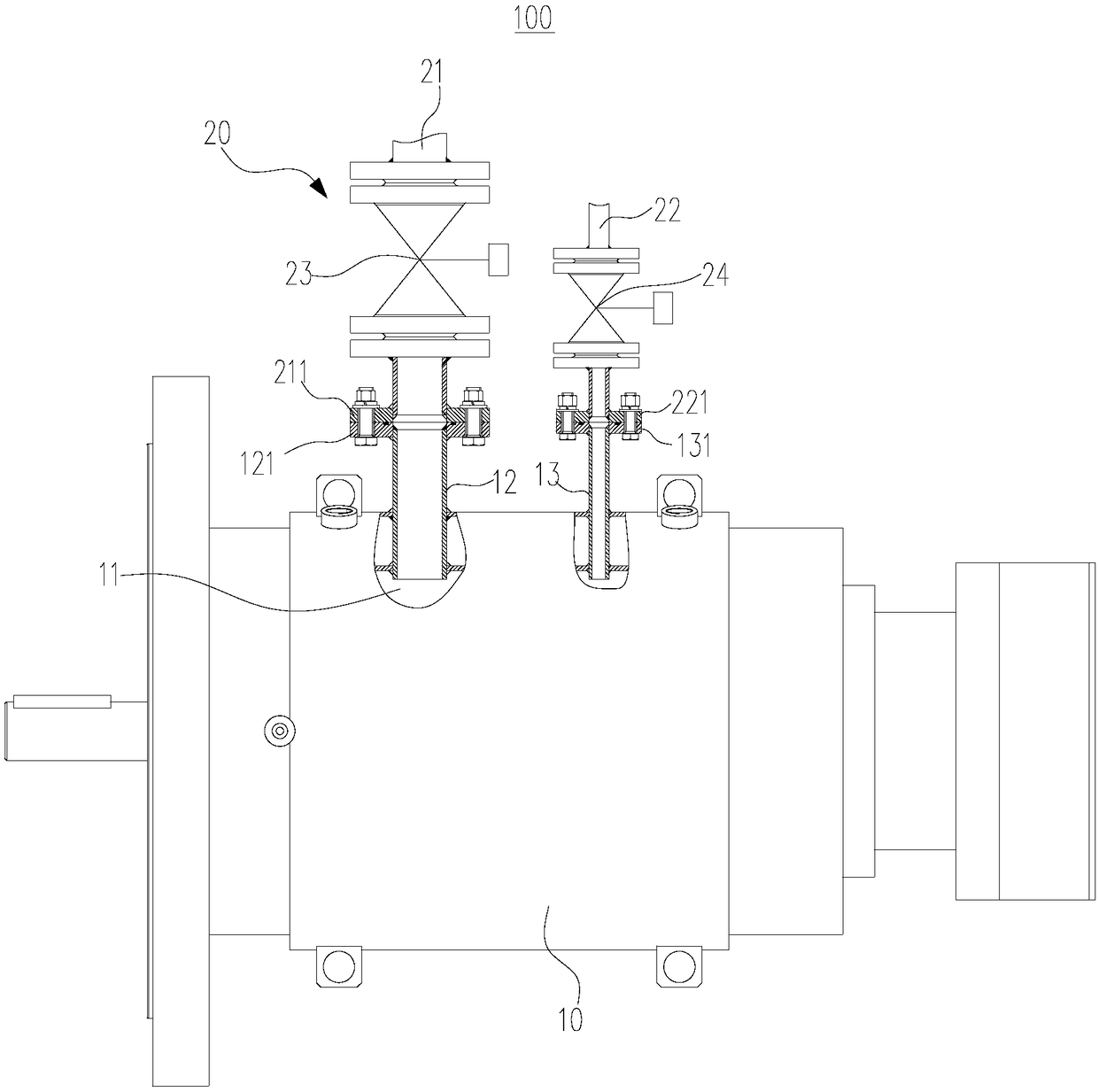
[0046] Such as figure 1 As shown, the present embodiment provides a vacuum starting system, including a motor 10 and an air supply device 20 , and the air supply device 20 is used to supply air to the inside of the motor 10 .

[0047] Wherein, the motor 10 has an inner cavity 11 , and a first connecting pipe 12 and a second connecting pipe 13 are provided on the outer shell of the motor 10 . The first connecting pipe 12 is fixedly connected with the shell of the motor 10, and one end of the first connecting pipe 12 extends into the inner chamber 11, so that the first connecting pipe 12 communicates with the inner chamber 11, and the other end of the first connecting pipe 12 is provided with The first flange 121 . The second connecting pipe 13 is fixedly connected with the shell of the motor 10, and one end of the second connecting pipe 13 extends into the inner chamber 11, so that the second connecting pipe 13 communicates with the inner chamber 11, and the other end of the s...

Embodiment 2

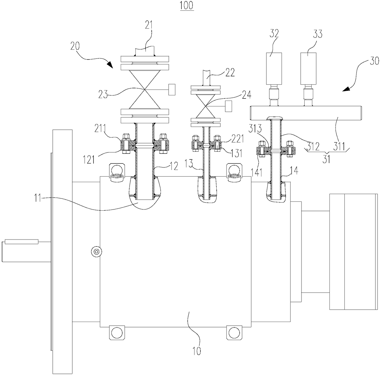
[0060] Such as figure 2 As shown, this embodiment provides a motor vacuum starting system 100, which is different from the above embodiments in that it further includes a detection device 30 and a control device.

[0061] The detection device 30 includes an outlet pipe 31 , a first pressure sensor 32 and a second pressure sensor 33 . Outlet pipe 31 comprises horizontal tube 311 and vertical tube 312, and horizontal bar is the structure that both ends are closed, and vertical tube 312 is perpendicular to horizontal tube 311, and one end of vertical tube 312 communicates with horizontal tube 311, and the other end of vertical tube 312 is provided with the first Five flanges 313. Both the first pressure sensor 32 and the second pressure sensor 33 are connected to the horizontal pipe 311 of the outlet pipe 31 . In this embodiment, the models of the first pressure sensor 32 and the second pressure sensor 33 are PT124G-210.

[0062] In this embodiment, a third connecting pipe 14...

Embodiment 3

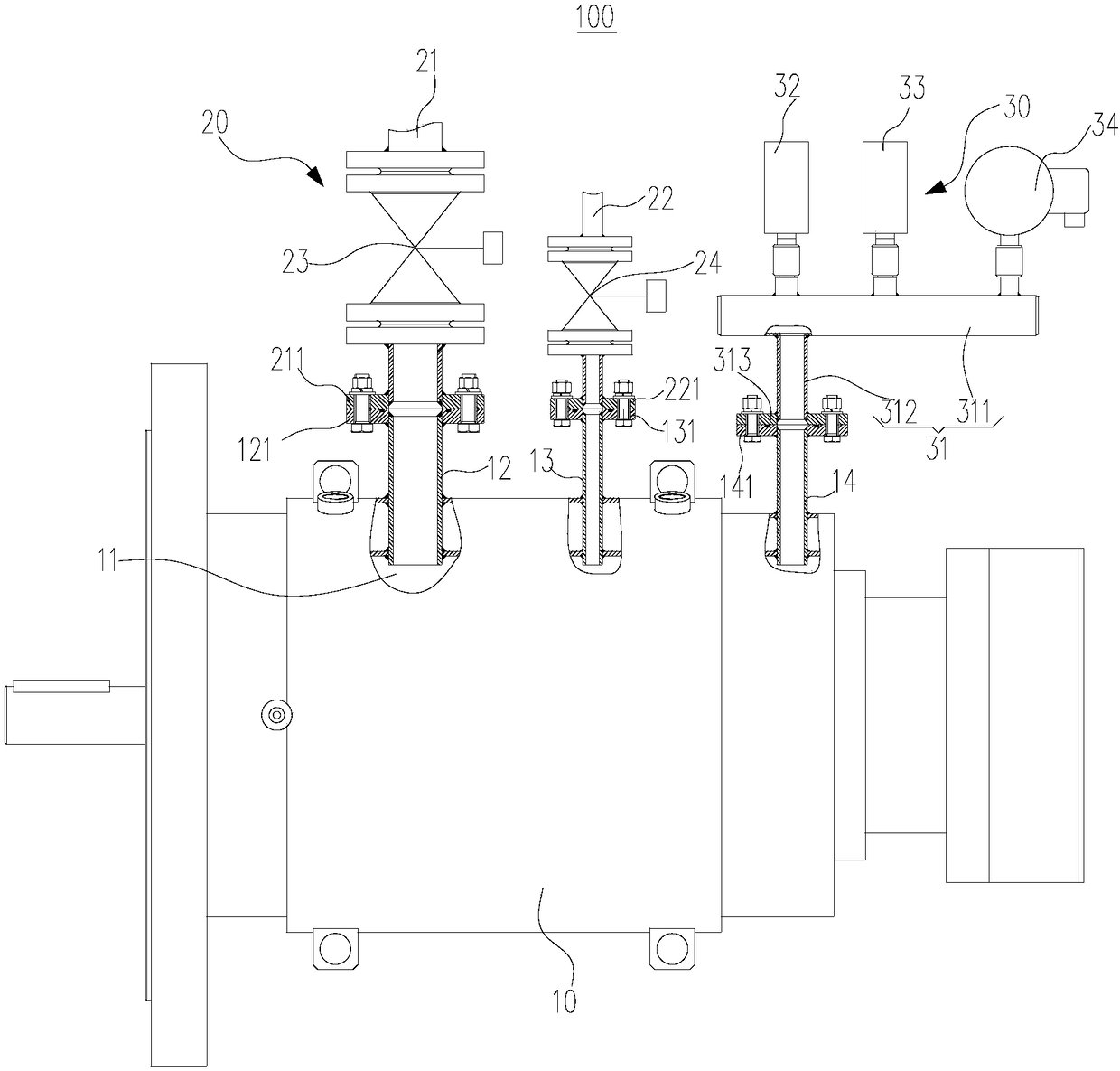
[0070] Such as image 3 As shown, this embodiment provides a motor vacuum starting system 100 , the difference from Embodiment 2 is that the detection device 30 also includes an electric contact pressure gauge 34 and an alarm device 35 .

[0071] In this embodiment, the electric contact pressure gauge 34 is connected to the horizontal pipe 311 of the outlet pipe 31 , and the electric contact pressure gauge 34 is used to detect the pressure inside the outlet pipe 31 .

[0072] In this embodiment, the alarm device 35 is a buzzer alarm, and the electric contact pressure gauge 34 is electrically connected to the buzzer alarm. Specifically, such as Figure 4 As shown, the electric contact pressure gauge 34 has a moving contact 341 and a static contact 342, and the moving contact 341 and the static contact 342 are connected in series in the circuit where the buzzer alarm is located. When the pressure value of the inner cavity 11 of the motor 10 reaches the third pressure value (se...


PUM


Abstract

The invention provides a motor vacuum startup system and a motor vacuum startup method and belongs to the technical field of metal thermal treatment equipment. The motor vacuum startup system comprises a motor and a gas supply device; the motor has an inner cavity; the gas supply device is communicated with an inner cavity; the gas supply device is used for supplying gas to the inner cavity. The motor vacuum startup system may ensure quick startup for the motor such that forceful cooling gas in a vacuum furnace is subjected to heat exchanging. In addition, the startup failure of the motor dueto the influence that the inside of the vacuum furnace is vacuum is avoided, and therefore, quenching quality is effectively ensured for a workpiece in the vacuum furnace.

Description

technical field [0001] The invention relates to the technical field of metal heat treatment equipment, in particular to a motor vacuum starting system and a motor vacuum starting method. Background technique [0002] Vacuum furnace is regarded as one of the equipments for upgrading equipment in the heat treatment industry. The important reason is that the product parts processed by vacuum furnace have bright surface, less oxidation, good performance and high precision. It is easy to realize energy saving, consumption reduction and reduction in the production and operation of vacuum furnace. It belongs to clean production equipment and meets the requirements of today's environmental protection. There are very few gas molecules in vacuum, and the free path of molecules becomes larger, so light rare metals, refractory metals, rare metals and other special alloy materials that cannot be obtained under normal pressure can be produced. [0003] Compared with traditional metallurg...

Claims


Application Information

Patent Timeline
IPC IPC(8): H02P1/02C21D1/773
CPCH02P1/02C21D1/773
Inventor 袁建锋朱楼飞
Owner 江苏石川岛丰东真空技术有限公司
Why Eureka
Try Eureka