


Quick Research
Generate reliable direction feasibility study reports for your R&D in just a few steps.

Technical Q&A
Discover and master advanced knowledge NOW. Basics, ideas, possibilities, all at once.

Find Solutions
As an expert in R&D theories, this can generate solutions to your technical problems instantly.

Evaluate Feasibility
Analyze your overall solution with one click, know your potential R&D risks in advance.

Monitor Landscape
Get weekly tech updates, stay abreast of the latest tech innovations and key insights.
Sampling time mismatch calibration device and method, and time interleaving analog-to-digital converter
A sampling time and calibration device technology, applied in analog-to-digital converters, analog-to-digital conversion, code conversion, etc., can solve problems such as unable to calibrate normally, achieve fast calibration speed, and expand the effect of applicable occasions
- Summary
- Abstract
- Description
- Claims
- Application Information
AI Technical Summary
Problems solved by technology
Method used
Image

Examples
Embodiment 1
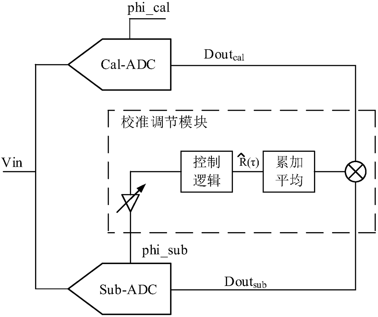
[0039] like Figure 5 As shown, the sampling time mismatch calibration device involved in this embodiment includes a reference channel 1, several sampling sub-channels 2 (only one sampling sub-channel 2 is shown in the figure for simplicity of illustration) and a calibration adjustment module 3, the reference channel 1. The sampling sub-channels 2 are electrically connected to the calibration adjustment module 3. The sampling time mismatch calibration device also includes a pseudo-random level generator 4, which is connected to the reference channel 1 and the sampling sub-channel 2 respectively. Electrically connected, the pseudo-random level generator 4 is used to generate the pseudo-random level Vth corresponding to each reference clock phi_cal, and the reference channel 1 is used to control the received analog signal Vin and the pseudo-random level under the control of the reference clock phi_cal Vth is sampled, and the first polarity signal D is output to the calibration a...
Embodiment 2
[0047] like Figure 7 As shown, the sampling time mismatch calibration device involved in this embodiment is based on the embodiment 1. During specific implementation, the reference channel 1 adopts the circuit form of a comparator to realize the function described in the embodiment 1, that is, the reference Channel 1 includes the first comparator A1, the positive input terminal of the first comparator A1 receives the analog signal Vin, the negative input terminal of the first comparator A1 receives the pseudo-random level Vth, the output terminal of the first comparator A1 is connected with the calibration adjustment Module 3 is electrically connected, and the first comparator A1 outputs the first polarity signal D under the control of the reference clock phi_cal 1 . By using a simple circuit form such as a comparator, the function of reference channel 1 can be realized, which not only eliminates the influence of ADC quantization error on calibration, that is, calibration is...
Embodiment 3
[0052] like Figure 8 As shown, the sampling time mismatch calibration method involved in this embodiment includes:
[0053] Step 101, the pseudo-random level generator generates a pseudo-random level corresponding to each reference clock;
[0054] Step 102, the reference channel samples the received analog signal and the pseudo-random level respectively under the control of the reference clock, and outputs the first polarity signal after comparing the sampling results;
[0055] Step 103, the sampling sub-channel samples the received analog signal and the pseudo-random level respectively under the control of the sub-sampling clock, and outputs a second polarity signal after comparing the sampling results;
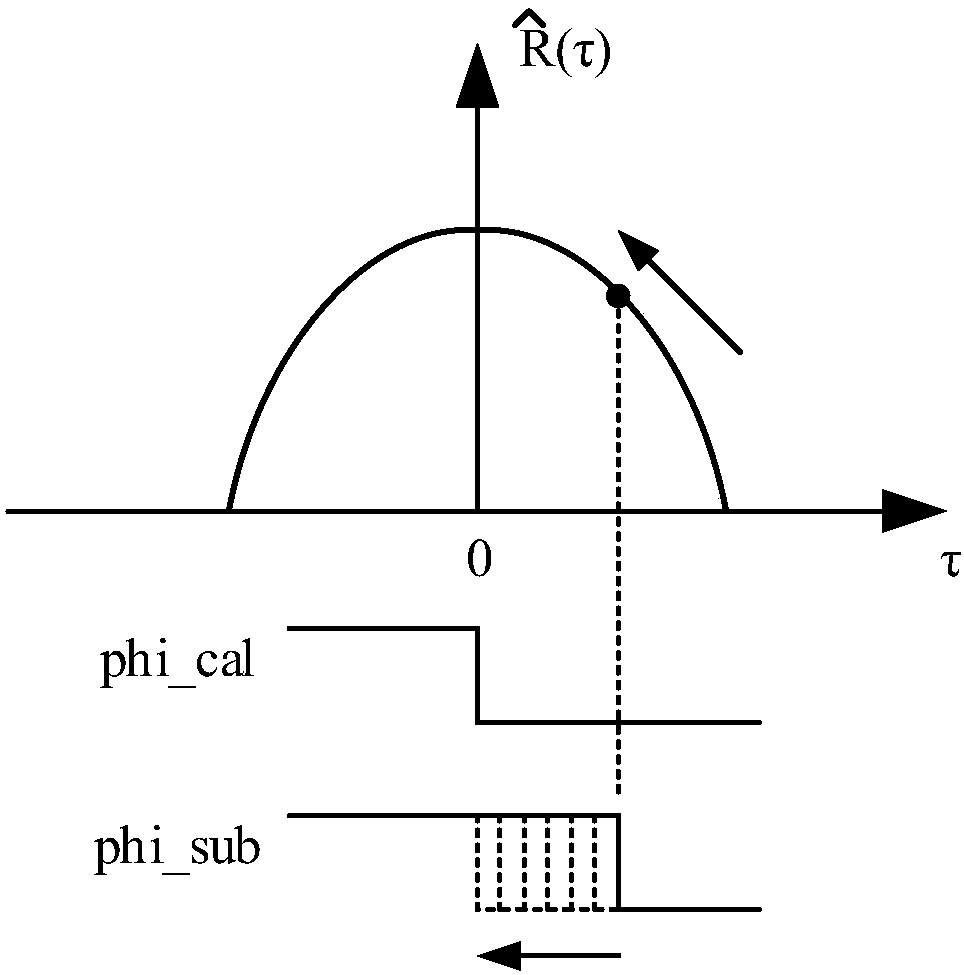
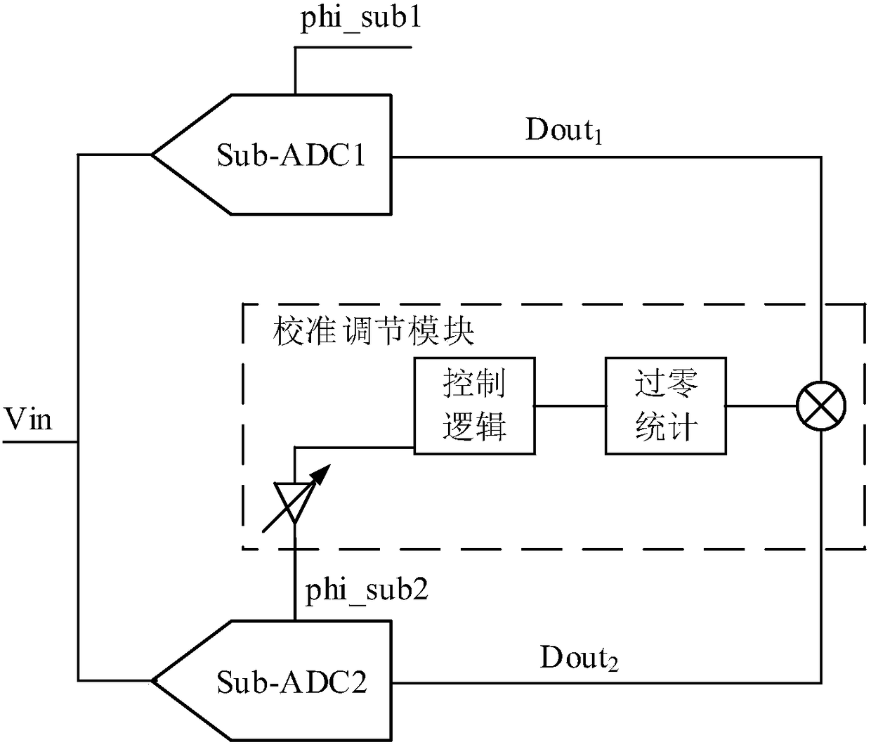
[0056] Step 104, the calibration adjustment module counts the number of zero-crossing points between the sampling sub-channel and the reference channel within a period of time according to the first polarity signal and the second polarity signal, and adjusts the The amoun...
PUM
 Abstract
Description
Claims
Application Information
 - R&D Engineer
- R&D Manager
- IP Professional
- Industry Leading Data Capabilities
- Powerful AI technology
- Patent DNA Extraction
Browse by: Latest US Patents, China's latest patents, Technical Efficacy Thesaurus, Application Domain, Technology Topic, Popular Technical Reports.
© 2024 PatSnap. All rights reserved.Legal|Privacy policy|Modern Slavery Act Transparency Statement|Sitemap|About US| Contact US: help@patsnap.com