
Heat Dissipation System And Fan Driving Circuit

一种散热系统、驱动电路的技术,应用在电气元件、机器/发动机、多个电动机速度调节等方向,能够解决风扇驱动电路误差、系统电路错误当机、风扇无法转动等问题,达到散热稳定度提高、设计成本降低、提高良率的效果

Active Publication Date: 2018-07-13
ANPEC ELECTRONICS CORPORATION
View PDF5 Cites 0 Cited by
  • Summary
  • Abstract
  • Description
  • Claims
  • Application Information

AI Technical Summary

Problems solved by technology

Therefore, even if the control module provides the same control signal to stop the rotation of different fan modules, the fan drive circuits of different fan modules will have a certain degree of error, that is, there may be a chance that one fan module has stopped rotating, while the other If one fan module is still operating, it may even happen that one fan cannot rotate, while other fans continue to operate, so that the control module thinks that the system is still operating normally
In this case, it is easy to cause uneven heat dissipation, and cause the system circuit to malfunction

Method used


Image

  • Heat Dissipation System And Fan Driving Circuit
  • Heat Dissipation System And Fan Driving Circuit
  • Heat Dissipation System And Fan Driving Circuit

Examples


Embodiment Construction

[0038] Various exemplary embodiments will be described more fully hereinafter with reference to the accompanying drawings, in which some exemplary embodiments are shown. However, inventive concepts may be embodied in many different forms and should not be construed as limited to the illustrative embodiments set forth herein. Rather, these exemplary embodiments are provided so that this disclosure will be thorough and complete, and will fully convey the scope of the inventive concept to those skilled in the art. In the drawings, the size and relative sizes of layers and regions may be exaggerated for clarity. Like numbers indicate like components throughout.

[0039] It will be understood that although the terms first, second, third etc. may be used herein to describe various components, these components should not be limited by these terms. These terms are used to distinguish one component from another. Thus, a first component discussed below could be termed a second compon...


PUM


Abstract

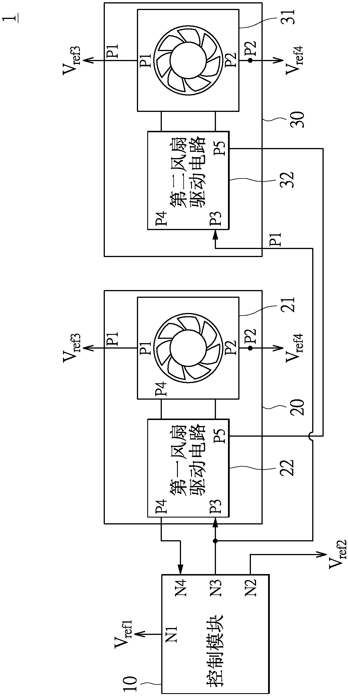
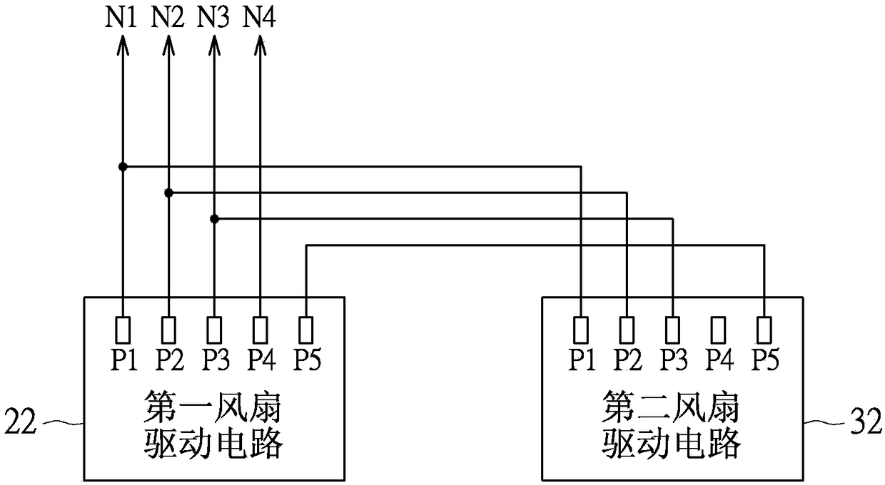
A heat dissipation system includes a control module, a first fan module and a second fan module. The first fan module is electrically connected to the control module to provide a speed signal to the control module. The second fan module is electrically connected to the control module and the first fan module. The control module provides at least one control signal to control the rotation of the first fan module and the second fan module respectively. The first fan module transmits a first trigger signal to the second fan module, and the second fan module starts to rotate or stops rotating together with the first fan module according to the first trigger signal.

Description

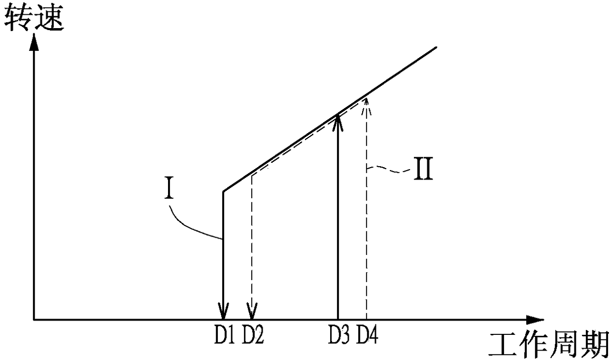
technical field [0001] The invention relates to a heat dissipation system and a fan drive circuit, in particular to a heat dissipation system and a fan drive circuit that can provide high stability. Background technique [0002] With the vigorous development of electronic devices in recent years, cooling systems have been widely used, and it is normal to use multiple fan modules as the design structure of the cooling system. However, to control different fan modules, due to the differences in the control circuit process, the control The method also needs to be adjusted correspondingly, so that different fan modules can act simultaneously as much as possible. [0003] Please refer to figure 1 , figure 1 It is a schematic diagram of the rotational speed curve of a general cooling system with multiple fans. exist figure 1 Among them, the rotation speed curve I and the rotation speed curve II are the rotation speed curves of different fan modules respectively. In the rotati...

Claims


Application Information

Patent Timeline
Patent Type & Authority Applications(China)
IPC IPC(8): H05K7/20F04D27/00
CPCF04D27/00H05K7/20209F04D25/166H02P5/46H02P6/04F04D25/0693F04D27/004Y02B30/70H05K7/20836
Inventor 陈昆民赖璟锋王建升
Owner ANPEC ELECTRONICS CORPORATION
Learn More