Clamp tool of tightening arm

A fixture and tooling technology, which is applied in the field of clamping and tooling of the tensioning arm, can solve the problems of discounted pin positioning effect, failure to meet parallelism requirements, large impact and vibration, etc., achieve convenient positioning effect, improve fixing effect, and reduce shaking Effect

Active Publication Date: 2018-07-17
YUHUAN ZHONGBEN MACHINERY
View PDF9 Cites 3 Cited by
  • Summary
  • Abstract
  • Description
  • Claims
  • Application Information

AI Technical Summary

Problems solved by technology

However, with the development of technology, the parallelism requirements of the shaft hole and the pin shaft are getting higher and higher, and the existing technology and tooling can no longer meet the higher parallelism requirements.
[0006] For this reason, technicians added positioning tooling during riveting, that is, positioning the pin shaft before riveting. However, due to the large impact and vibration caused by riveting, the positioning effect of the positioning tooling on the pin shaft during the riveting process is often big discount
Or modify the pin shaft and shaft hole after riveting, but there is no ready-made tooling available, and a new fixture tooling needs to be designed

Method used


Image

  • Clamp tool of tightening arm
  • Clamp tool of tightening arm
  • Clamp tool of tightening arm

Examples


Embodiment 1

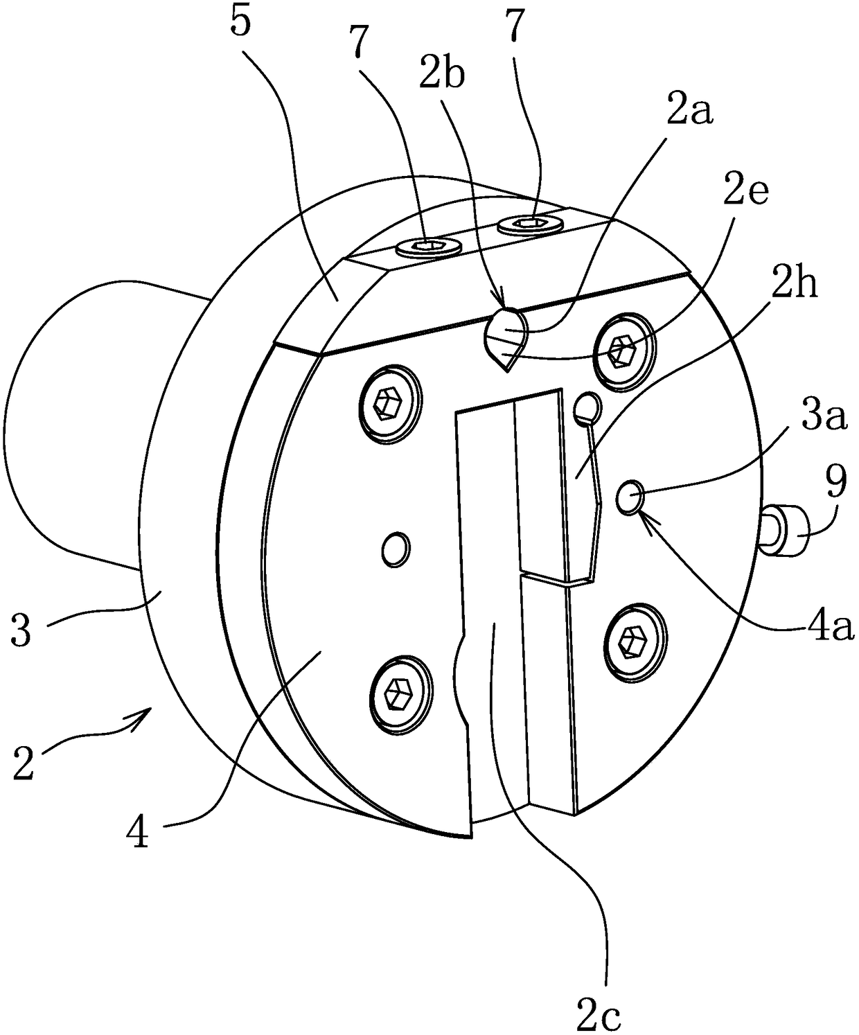
[0039] Such as Figure 2-Figure 6 As shown, a clamp tooling for a tensioning arm includes a connecting seat 2 that can rotate. A pressure plate 5 is provided on the front side of the connecting seat 2 through a pressing member. The contact surface of the connecting seat 2 and the pressure plate 5 The shape is the same, and the mounting hole 2b and mounting hole 2b for clamping the pin 1d in the tensioning arm 1 are formed by opening a straight groove 2a on the contact surface of the connecting seat 2 or / and the pressure plate 5 between the two The axial direction of is parallel to the rotation axis of the connecting seat 2. The straight groove 2a is an arc-shaped groove for mating with the pin shaft 1d, and a strip-shaped relief groove 2e is provided on the bottom surface of the straight groove 2a. A spacer 6 is fixed in the mounting hole 2b so that the axial depth of the mounting hole 2b is smaller than the axial length of the pin shaft 1d. The edge of the mounting hole 2b is...

Embodiment 2

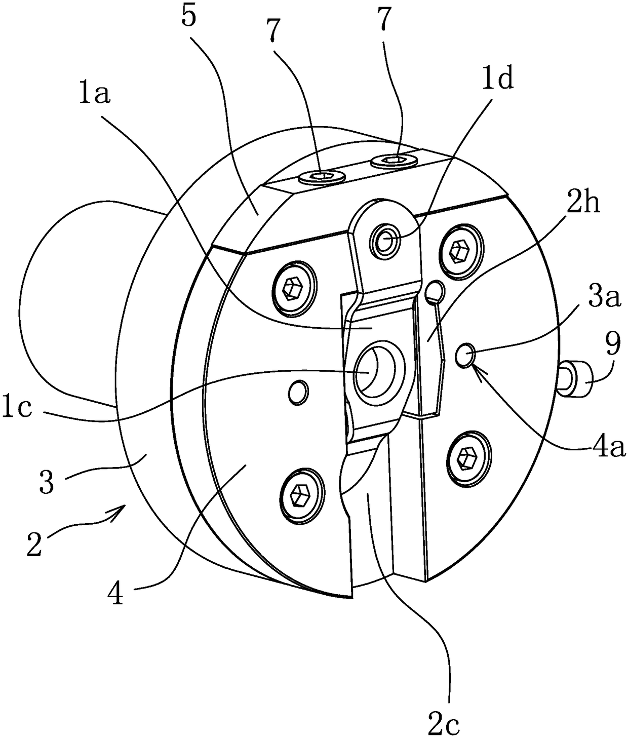
[0045] Such as Figure 7 As shown, the front end surface of the connecting seat 2 is provided with a stopper 2d into which the main body 1a of the tensioning arm 1 is placed to prevent swinging around its pin 1d, and an abutting member 2h is provided on the connecting seat 2 at the stopper 2d, A push rod 9 is connected to the connecting base 2. One end of the abutment member 2h can be fixed to the connecting seat 2, and one end of the push rod 9 abuts on the abutment member 2h; the abutment member 2h can be separated from the connection seat 2, and the abutment member 2h is connected to one end of the push rod 9. The other structure is the same as the first embodiment.

Embodiment 3

[0047] The pressing part is a pressing cylinder, and the piston rod of the pressing cylinder is fixedly connected with the pressing plate 5. The push rod 9 is a straight rod, a positioning cylinder is connected to the push rod 9, and the piston rod of the positioning cylinder is fixedly connected with the push rod 9. Both the compression cylinder and the positioning cylinder are electrically connected to the control panel of the machine tool to realize automatic clamping and improve production efficiency. The other structure is the same as the first embodiment.


PUM


Abstract

The invention provides a clamp tool of a tightening arm, and belongs to the technical field of machines. The problem that due to an existing tightening arm clamp tool, the parallelism error between apin shaft and a shaft hole of a tightening arm is large is solved. The clamp tool of the tightening arm comprises a connecting seat capable of rotating, and a pressing plate pressed on the connectingseat through a compressing part is arranged on the side face of the front end of the connecting seat. The contact faces of the connecting seat and the pressing plate are consistent in shape, and a mounting hole for clamping the pin shaft of the tightening arm is formed between the connecting seat and the pressing plate in the manner of forming a straight groove in the contact faces of the connecting seat or / and the pressing plate. The axial direction of the mounting hole is parallel to the rotating axial direction of the connecting seat, and a concave cavity or stop dog allowing a tightening arm body to be placed in for preventing the tightening arm body from swinging around the pin shaft is arranged on the front end face of the connecting seat. According to the clamp tool of the tightening arm, the parallelism degree between the shaft hole and the pin shaft of the tightening arm can be improved.

Description

Technical field [0001] The invention belongs to the technical field of machinery and relates to a clamp tooling for a tensioning arm. Background technique [0002] The engine equipment of motorcycles uses the timing chain to drive the valve system to work, but the chain will slack during use, so a tensioner is often installed on the engine equipment, and the chain is tightened through the tensioner. [0003] Such as figure 1 As shown, the tensioning arm 1 includes a main body 1a, the middle of the main body 1a has a shaft cylinder 1b, the shaft cylinder 1b is provided with a shaft hole 1c, one end of the main body 1a is provided with a pin hole, and a pin is inserted and fixed in the pin hole The shaft 1d, the other end of the main body 1a is provided with a spring mounting head 1e, and the pin shaft 1d is sleeved and fixed with a tensioner. When installing the tensioning arm 1, install the tensioning arm 1 on the fixed shaft through the shaft hole 1c, and a tensioning spring is f...

Claims


Application Information

Patent Timeline
Patent Type & Authority Applications(China)
IPC IPC(8): B23Q3/06
CPCB23Q3/062
Inventor 高源浩陈仕忠
Owner YUHUAN ZHONGBEN MACHINERY
Why Eureka
Try Eureka