Eureka AIR delivers breakthrough ideas for toughest innovation challenges, trusted by R&D personnel around the world.

Warm-air pipe

A technology of hot air ducts and air ducts, applied in lighting and heating equipment, dryers, drying, etc., can solve the problems of air ducts that cannot quickly disperse gas, weak gas circulation capacity, and uneven products, and achieve guaranteed The consistency and stability of temperature, the effect of reducing wind vortex and stabilizing temperature

Pending Publication Date: 2018-07-17
SHENZHEN SENIOR TECH MATERIAL
View PDF0 Cites 0 Cited by
  • Summary
  • Abstract
  • Description
  • Claims
  • Application Information

AI Technical Summary

Problems solved by technology

[0003] In the process of high temperature requirements in industrial production, the consistency and stability of the internal temperature of the oven will determine the quality of the product and the production process capability. There are still deficiencies in control, which directly lead to product stability and consistency of some industrial products, resulting in uneven products. The existing air duct structure inside the heat treatment oven is single, the gas circulation capacity is weak, and the single design of the air duct After the gas enters the heat treatment oven, it cannot disperse quickly

Method used


Image

  • Warm-air pipe
  • Warm-air pipe
  • Warm-air pipe

Examples


no. 1 example

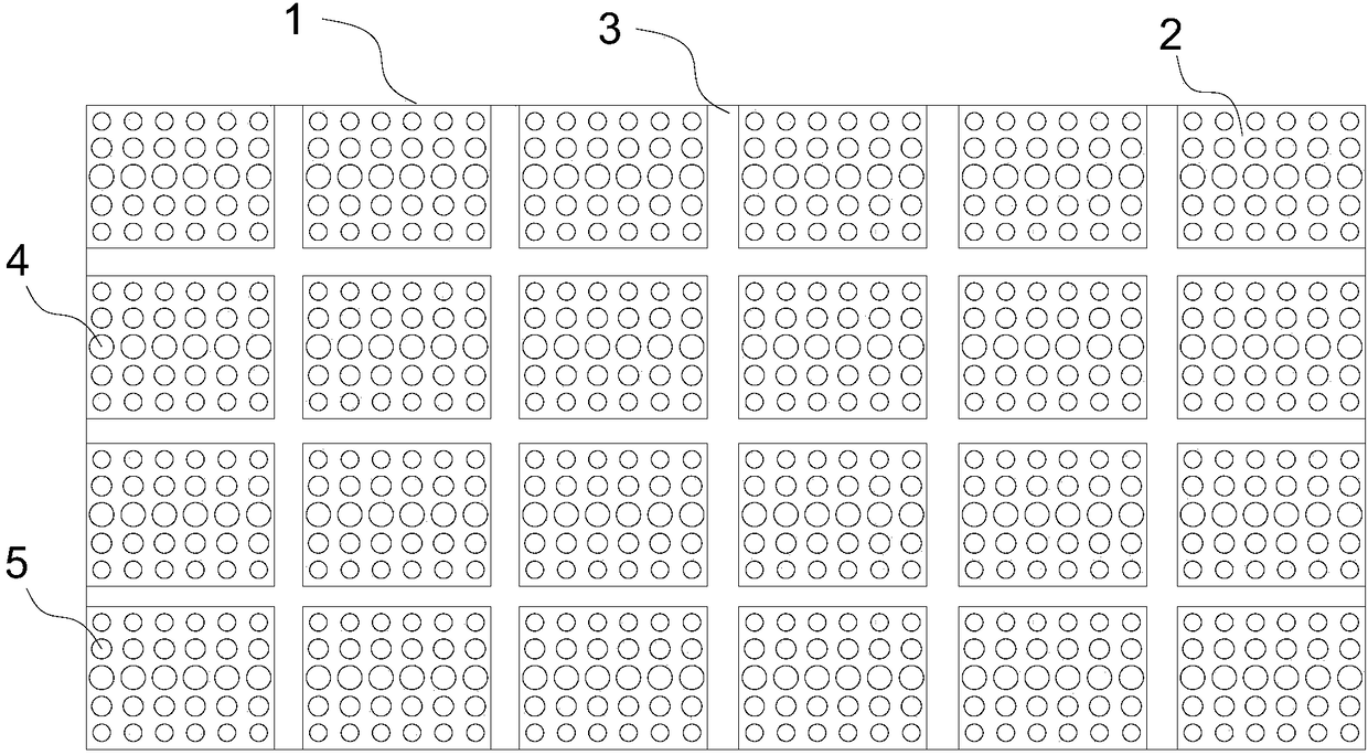
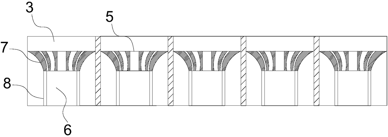
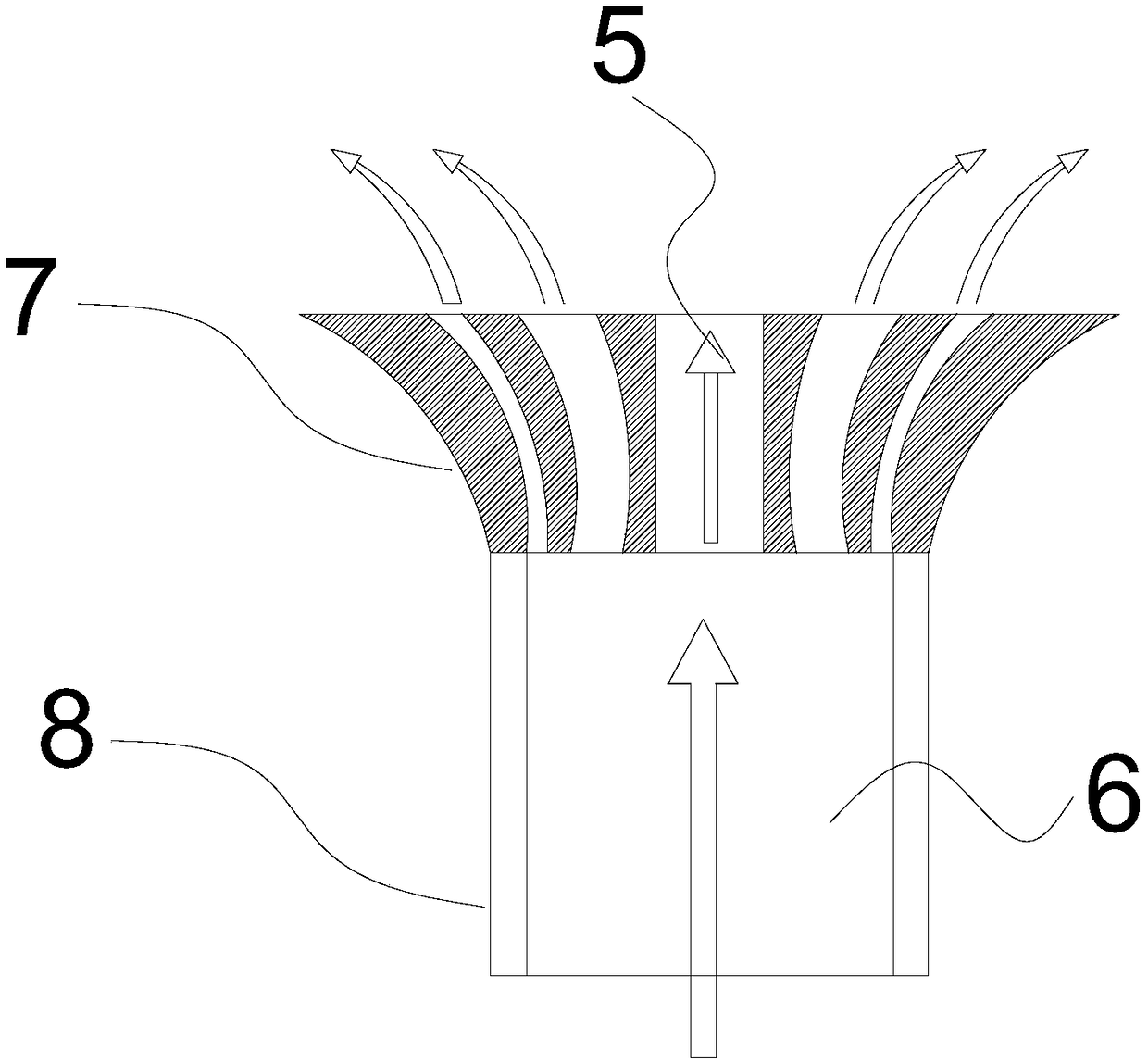
[0030] Please refer to figure 1 , attached figure 2 , the present embodiment provides a hot air duct 1, which is applied to a heat treatment oven, including an air duct 2, the material of the air duct 2 is stainless steel or aluminum, stainless steel will not rust, corrosion resistance, high temperature resistance, long service life; aluminum The air duct 2 is light in weight, easy to disassemble and install, easy to process, does not change color, and is not easy to deform; one end of the air duct 2 is an air inlet 8, and the other end of the air duct 2 is an air outlet 7, and the shape of the air inlet 8 is a rectangle or a cylinder The shape of the air outlet 7 is a trumpet shape with a large outer end surface and a small inner side, which facilitates the outflow of gas and ensures the stability of the air volume and wind pressure. The air inlet 8 of the air duct 2 is provided with a main chamber 6 for gas entry. , the gas enters and flows from the main cavity 6 to the ai...

no. 2 example

[0033] Please refer to image 3 , attached Figure 4 , combined with figure 1 , figure 2, the present embodiment provides a hot air pipe 1, which is applied to a heat treatment oven. The circular centers of the directions are on the same straight line, each row of air chambers 4 is evenly arranged inside the air outlet 7, and the sub-chambers 5 on each row of air chambers 4 are correspondingly distributed on the end faces of the air outlet 7.

[0034] The gas flows from the main chamber 6 of the air inlet 8 to the air outlet 7, and the gas is dispersed into multiple strands at the air outlet 7, and flows out from the sub-chambers 5 at different positions respectively. The air chambers 4 in the air outlet 7 are evenly arranged, and each air exhaust The sub-chambers 5 at the same position of the chamber 4 are equal in size, and the gas discharge of the sub-chambers 5 on the straight line perpendicular to the air chamber 4 is relatively uniform. The diameter of the middle sub...


PUM


Abstract

The invention discloses a warm-air pipe and relates to the field of temperature control. The warm-air pipe is applied to a thermal treatment oven. The warm-air pipe comprises a plurality of air pipes,wherein one end of each air pipe is an air inlet while the other end of each air pipe is an air outlet; a main cavity where gas flows in is formed in the air inlet end of the air pipe; a plurality ofair cavities where gas flows out are arranged in the air outlet; each row of the air cavities is composed of more than three sub cavities; the diameter of the sub cavity in the middle of the air cavity is greater and the diameters of the sub cavities at two ends are small; the warm-air pipe comprises air pipes which are fixed one another and same in directions of air inlets; the warm-air pipe canreduce air flow vortex effectively and reduce fluctuation of a temperature field in the process of conveying gas, so that the stability and consistency of temperature in the thermal treatment oven are guaranteed.

Description

technical field [0001] The invention relates to the field of temperature control equipment, in particular to a hot air pipe. Background technique [0002] With the development of industrialization, refined management has become an irreversible trend. As a component often used in industrial production, the heat treatment oven is designed with the internal structure of the hot air pipe in the oven to ensure the temperature distribution and temperature stability inside the oven. The property has a decisive influence, and the hot air pipe controls the gas flow in the oven, so as to control the temperature in the heat treatment oven. [0003] In the process of high temperature requirements in industrial production, the consistency and stability of the internal temperature of the oven will determine the quality of the product and the production process capability. There are still deficiencies in control, which directly lead to product stability and consistency of some industrial ...

Claims


Application Information

Patent Timeline
Patent Type & Authority Applications(China)
IPC IPC(8): F26B21/00
CPCF26B21/004
Inventor 张德林刘孟权陈秀峰陈良
Owner SHENZHEN SENIOR TECH MATERIAL
Why Eureka
Eureka Blog
Learn More